Device for pressure tapping and procedure for setting it on a fuselage panel of an aircraft

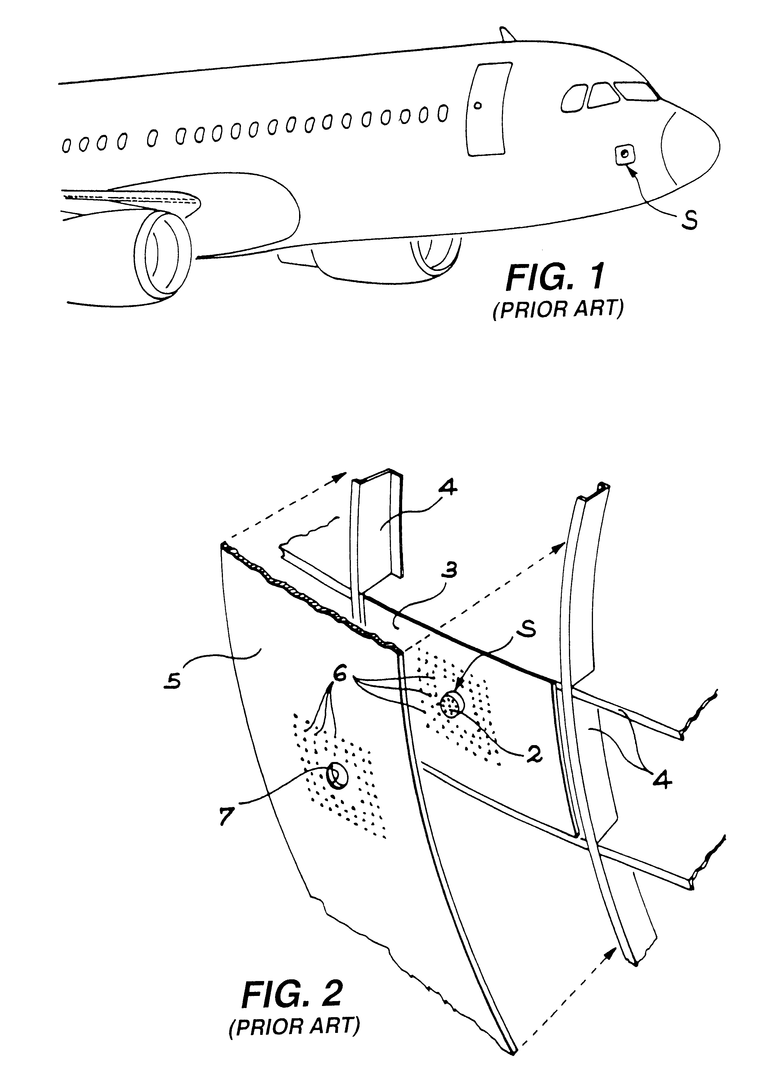
a technology for aircraft fuselage and devices, applied in the direction of aircraft floors, fluid speed measurement using pressure difference, indication/recording movement, etc., can solve the problems of loss of precision of the probe, the operation of levelling devices after mounting them is an industrially complicated operation, and the operation requires great precision and therefore a lot of tim

Inactive Publication Date: 2002-09-03
EADS AIRBUS
View PDF6 Cites 12 Cited by
  • Summary
  • Abstract
  • Description
  • Claims
  • Application Information

AI Technical Summary

Benefits of technology

Since the part for pressure tapping is integrated, without discontinuity, into a plate of relatively large dimensions, the continuity of the aerodynamic profile of the fuselage is ensured in the measurement zone surrounding the part for pressure tapping, without any machining being necessary. In addition, it becomes possible to fix this plate on the support element from the outside of the aircraft, in an opening in the fuselage panel, whose shape and dimensions are adapted to those of the plate. This method of fixation makes it possible to adjust the plate easily in such a way that its external surface is flush with the external surface of the fuselage panel without any levelling operation being required. In fact, the flush tolerance is much less strict at the edge of the plate than in the measurement zone. Thus, a much simpler and much faster mounting can be made. In addition, the replacement of a pressure tapping part which may be damaged following a shock is also simpler and faster.
Moreover, since this technique makes it possible to guarantee the continuity of the external surface of the aircraft fuselage in the measurement zone located close to the pressure tapping part, the quality and precision of the measurement are naturally improved.
Besides this, slight damage to the plate integrating the pressure tapping part, such as a scratch, can be remedied by simply replacing this plate. If the damage is to the fuselage panel, the defect is sufficiently far away from the pressure tapping part so as not to cause any disturbance in the measurement.
Advantageously, in order to be able to adjust the plate relative to the fuselage panel, during fixation of said plate on the support element, shims are used. This makes it possible, without difficulty, to ensure with precision that the external surfaces of the plate and the fuselage panel are flush.
Advantageously, the plate is then fixed onto the support element by fixation elements, such as screws or bolts, which are all arranged around the edge of the plate. The fixation elements are thus at a distance from the measurement zone located near the pressure tapping part. This contributes to guaranteeing the quality and precision of the measurement made by the probe.

Problems solved by technology

First of all, the machining of a small circular opening 7 in the fuselage panel 5 causes deformation and thus significant stresses in this panel. The high number and setting of the rivets used to fix the panel 5 on the support element 3 accentuate this deformation. In addition, the heads of the rivets located in the immediate proximity of the pressure tapping part 2 of the device S contribute to local disturbance of the aerodynamic flow. This results in measurement errors and thus a loss of precision of the probe.
Moreover, the levelling operation carried out after mounting the device S is an industrially complicated operation.
In fact, since the tolerances are very low, this operation requires great precision and therefore a lot of time.
If it is carried out poorly, the probe will deliver inexact measurements, which is not acceptable as mentioned above.
Another inconvenience of the technique for setting the device S used at present appears when it is damaged in the event of a shock.
Replacement is thus lengthy and difficult.
In the hypothesis where the fuselage panel is slightly damaged close to the device S, it is not worth replacing it.
Nonetheless, a simple scratch on the panel modifies the local aerodynamic flow and falsifies the measurement.
Again, this is an industrially complicated operation and is delicate to manage.
This evolution makes the utilisation of existing pressure measurement devices more and more delicate.

Method used


Image

  • Device for pressure tapping and procedure for setting it on a fuselage panel of an aircraft
  • Device for pressure tapping and procedure for setting it on a fuselage panel of an aircraft
  • Device for pressure tapping and procedure for setting it on a fuselage panel of an aircraft

Examples


Embodiment Construction

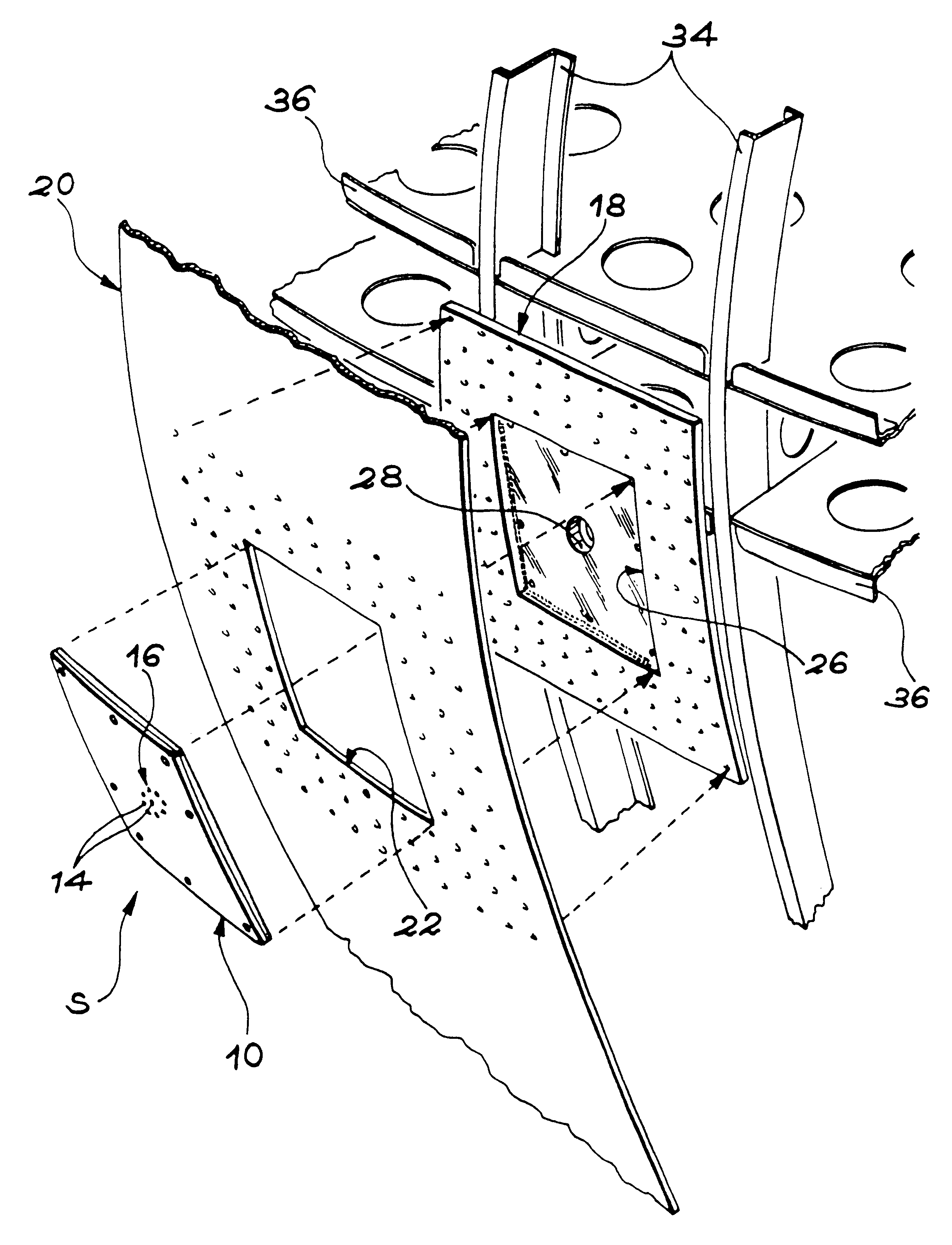
The aim of the present invention is a device for tapping pressure for an aircraft, with an original design which significantly improves the quality of the measurements made by the probe, at the same time making it quicker and simpler to be set on the fuselage panel, and to be changed if needed.

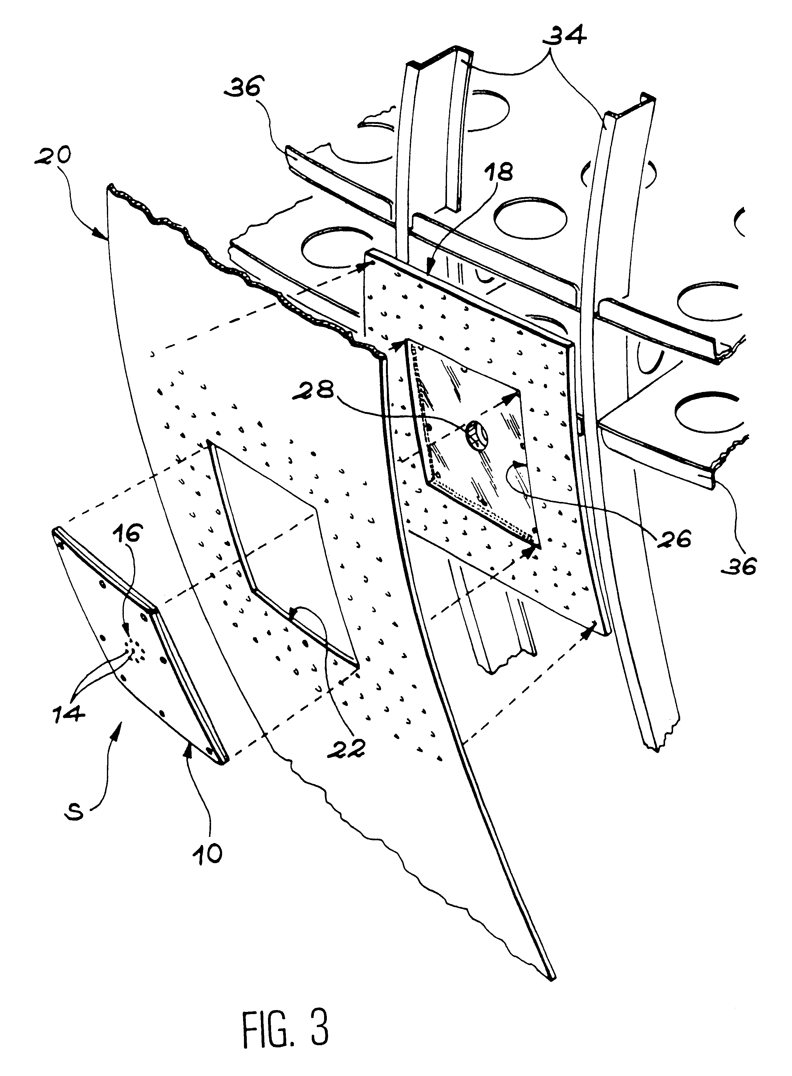
According to the invention, this result is obtained by means of a device for an aircraft for pressure tapping, comprising at least one support element, a part for pressure tapping carried by the support element and turned towards the outside of the aircraft, and a fuselage panel fixed on the support element and provided with an opening which receives the part for pressure tapping, a device characterised in that it also comprises a plate in which is integrated, without discontinuity, the part for pressure tapping, said plate being fixed on the support element and the opening having a shape and dimensions almost identical to those of the plate, in such a way that the latter is received in said o...


PUM


Abstract

Device for pressure tapping, integrated into the fuselage of an aircraft, comprising an integrated plate (10), without discontinuity, with a pressure tapping part in the center (16). The plate (10) enters a supplementary opening (22) formed in a fuselage panel (20). The plate (10) and the panel part (20) surrounding the opening (22) are fixed on a supporting element (18) linked to the framework of the aircraft (34, 36). In the case where rivet, screw or bolt type fixations are used, they are placed at the edge of the plate (10). This arrangement facilitates assembly and improves the precision of the measurement, by suppressing any discontinuity in the measurement zone.

Description

The present invention relates to a device for pressure tapping intended to be implanted on the fuselage of an aircraft.The invention also concerns a procedure for setting such a device for pressure tapping on a fuselage panel of an aircraft.STATE OF PRIOR ARTAircraft and in particular aeroplanes are equipped with different probes designed to measure a certain number of parameters. These parameters are then transmitted to the equipment, in such a way as to ensure correct operation of the aircraft and its instruments. Thus, certain probes, located near the combustion chamber, supply information making it possible to follow the behavior of the engine (temperature of gas ejection, rev / min, etc.). Other probes, installed under the fuselage, deliver information about the environment outside the aircraft (temperature, pressure, etc.).Among the probes installed under the fuselage of the aircraft, one finds probes for measuring static pressure. The information delivered by these probes makes...

Claims


Application Information

Patent Timeline
Patent Type & Authority Patents(United States)
IPC IPC(8): B64C1/00B64C1/14B64D43/02B64D43/00G01P13/02G01P5/14
CPCB64C1/1446B64D43/02G01P5/14G01P13/025
Inventor BOURGON, JEAN-MARCBAYONNE, SERGECHAUVEAU, BRUNO
Owner EADS AIRBUS
Why Eureka
Try Eureka