
Electronic whiteboard system eraser

Inactive Publication Date: 2002-09-03
POLYVISION CORP (US)
View PDF7 Cites 43 Cited by
  • Summary
  • Abstract
  • Description
  • Claims
  • Application Information

AI Technical Summary

Benefits of technology

It is a further object of this invention to provide such a system and such methods which allow the user to erase both the physical writing and erase or mark the electronic data representing the physical writing in an ergomonically sound manner.
It is a further object of this invention to provide such a system and such methods which allow the user to erase the physical writing and the electronic data representing the writing without the need to invoke an erase function, draw a circle around the information to be erased, invoke an erase command, and then physically erase the actual writing on the whiteboard.
It is a further object of this invention to provide such a system and such methods which automatically eliminate erroneous data.
This invention results from the realization that many of the data recording errors associated with writing and erasing actions on an electronic whiteboard can be eliminated by use of a circular and therefore orientation independent eraser with a central pointed protrusion which insures a positive initial contact of the eraser with the whiteboard; and / or also by the use of an electronic filter which detects and filters out data relating to contacts with the whiteboard not predictably associated with normal writing or erasing actions; and further that the filter constraints need to be changed and usually relaxed somewhat for erasing actions since people use an eraser in a fashion different than they use a writing instrument. This invention results from the further realization that the cumbersome prior art whiteboard erasing function wherein the user must first draw a circle around the writing to be erased in order for that writing to be electronically deleted can be eliminated by the use of the above described circular eraser with the central protrusion in conjunction with software or firmware which detects the occurrence of the user erasing the actual writing on the whiteboard and then simultaneously and automatically also erases or marks the stored electronic data representing the actual writing thereby rendering the electronic whiteboard more user friendly since writing and erasing, from the viewpoint of the user, occur just as if the user was writing on a chalkboard.
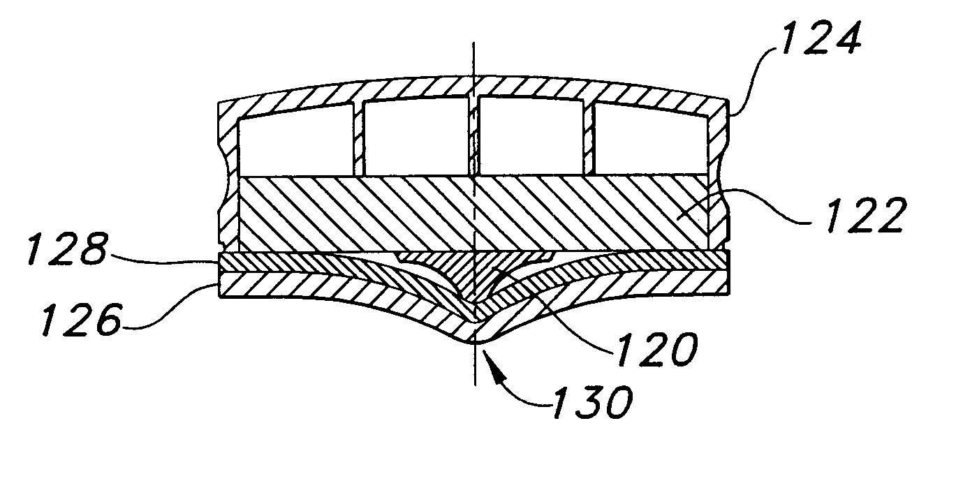
This invention features an eraser for use on an electronic whiteboard, the eraser comprising an erasing surface including at least one protrusion extending therefrom forming a convex area on the erasing surface. The erasing surface is typically circular shaped for eliminating the need to orient the eraser on the whiteboard in a predetermined manner and a cylindrical shaped foam body portion may be attached to the erasing surface. The protrusion is preferably centrally located on the erasing surface and has a surface area which is substantially less than the surface area of the erasing surface.

Problems solved by technology

Currently available electronic whiteboards, however, suffer from a few serious short comings.
Obviously, this time consuming and awkward process is a serious departure from the normal way erasing occurs on a typical blackboard and thus the user must be provided with detailed instructions regarding how to properly erase the stored digital information, and the audience must patiently wait for the presenter to complete all the erasing functions before the presentation can resume.
Another reason for this complex methodology is due to the fact that most erasers currently used are flat.
Since the typical user may alternately presses lightly and then more firmly and / or rock the erasure from side to side during each erase stroke, it is difficult for the electronics to accurately detect where and how much of the eraser surface is actually touching the whiteboard.
Another shortcoming in current electronic whiteboards systems is the data integrity problems which occur due to inadvertent contacts with the whiteboard.
The whiteboard electronics may accurately record the pen movement but will also erroneously record the contact of the user's hand with the whiteboard surface as a writing event.
The same type of data corruption can occur due to electronic noise generated by outside influences beyond the control of the electronics portion of the whiteboard system.
At printout or transmission, the corrupted data will thus not accurately match the actual writing on the whiteboard.

Method used


Image

  • Electronic whiteboard system eraser
  • Electronic whiteboard system eraser
  • Electronic whiteboard system eraser

Examples


Embodiment Construction

Other objects, features and advantages will occur to those skilled in the art from the following description of a preferred embodiment and the accompanying drawings, in which:

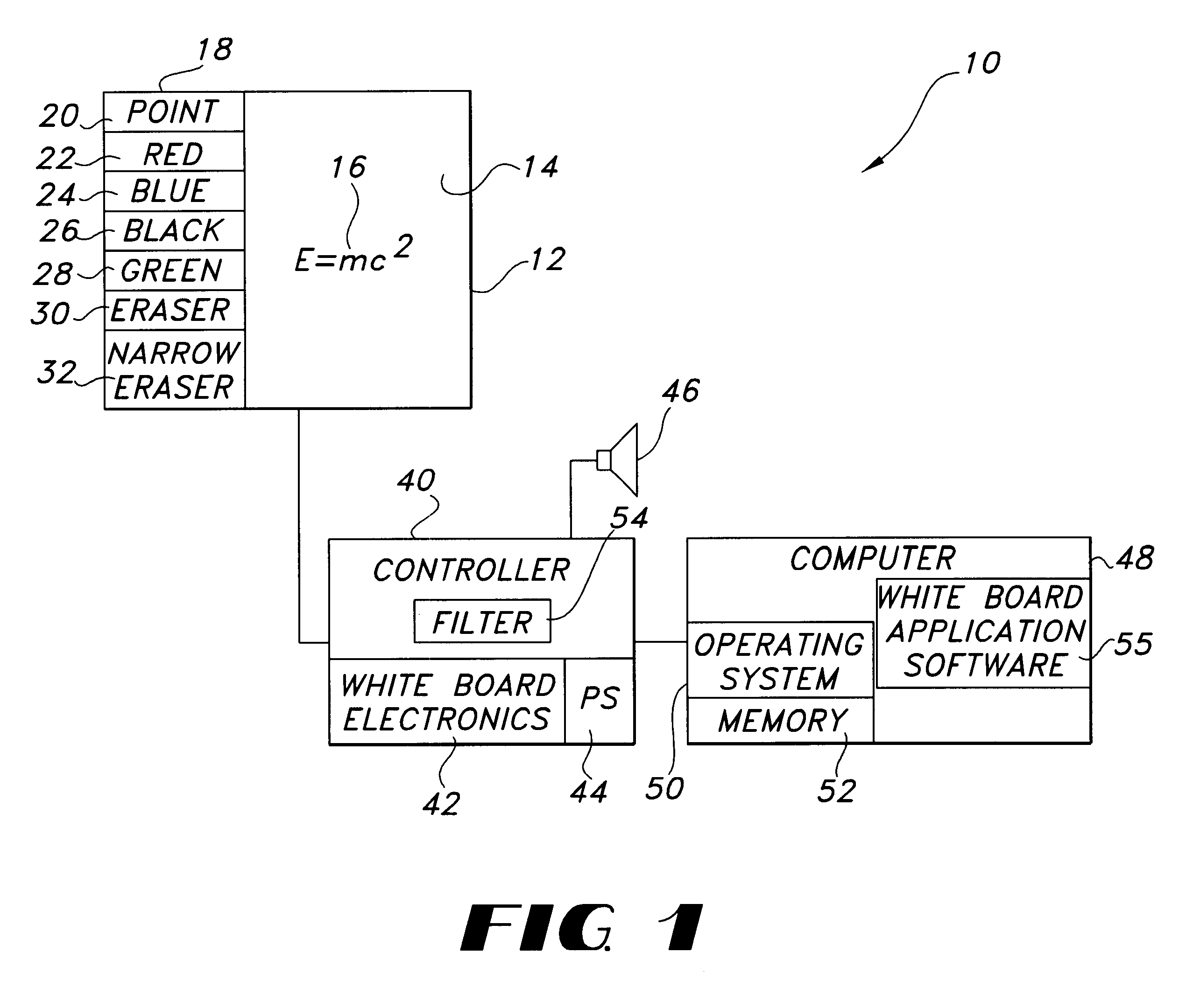
FIG. 1 is a block diagram showing the primary components of electronic whiteboard system of this invention;

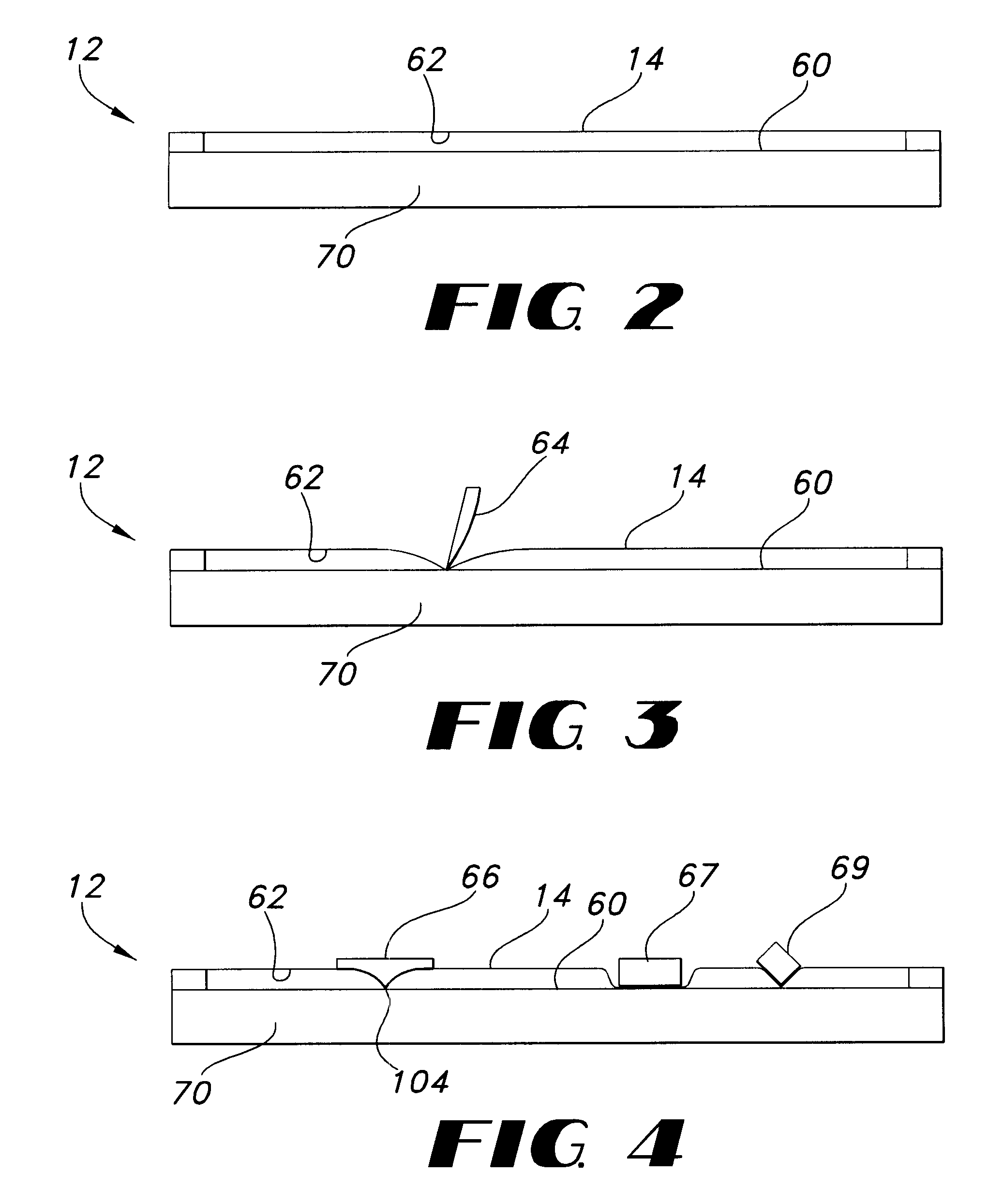
FIG. 2 is a side cutaway view of the digitizer portion of the electronic whiteboard system shown in FIG. 1;

FIG. 3 is a side cutaway view showing the use of a writing instrument such as a pen in conjunction with the digitizer shown in FIG. 2;

FIG. 4 is a side cutaway view showing the use of the eraser of this invention in conjunction with the digitizer shown in FIG. 2;

FIG. 5 is a schematic view of one embodiment of the eraser of this invention;

FIG. 6 is a cutaway view of another embodiment of the eraser for use on an electronic whiteboard in connection with this invention;

FIG. 7 is a cutaway view showing the configuration of an alternative erasure construction in accordance with this invention;

FIG. 8 is a sc...


PUM


Abstract

An eraser for use on an electronic whiteboard with a protrusion area on the erasing surface forming a convex area on the erasing surface for establishing a positive point of contact with the whiteboard; an electronic whiteboard system including such an eraser, a controller for storing data relating to information written on and erased from the whiteboard data, and a filter for preventing the storage of digital data relating to contacts with the whiteboard not attributable to normal writing or erasing actions.

Description

This invention relates to an electronic whiteboard system and method, and more particularly to a novel eraser for use on an electronic whiteboard, a data filtering control system for use in conjunction with an electronic whiteboard and a method of filtering errant data associated with electronic whiteboards.BACKGROUND OF INVENTIONElectronic whiteboards are currently gaining favor in the market place because they provide for electronic recordation of all figures, words and characters handwritten on the whiteboard for later printout, review, and / or transmission. Typical electronic whiteboards include a resistive membrane stretched over a rigid substrate, an electronics module for determining the position of the instrument such as a pen used to write on the whiteboard and a computer for processing and storing the coordinates of the pen as it moves over the whiteboard. Examples of currently available electronic whiteboard systems include those marketed by Smart Technology, Inc. of Calga...

Claims


Application Information

Patent Timeline
IPC IPC(8): G06F3/033G06F3/038
CPCG06F3/033G06F3/03543G06F3/038G06F3/0488
Inventor ATWOOD, STEPHENGEAGHAN, BERNARD
Owner POLYVISION CORP (US)
Learn More