Vapor system arrangement for marine engine

a technology of vapor system and marine engine, which is applied in the direction of electrical control, motor-driven power plants, special-purpose vessels, etc., can solve the problems of increasing the weight of the engine, increasing the emissions of the engine, and producing large amounts of carbon monoxide and hydrocarbons

Inactive Publication Date: 2002-09-10
YAMAHA MOTOR CO LTD
View PDF14 Cites 23 Cited by
  • Summary
  • Abstract
  • Description
  • Claims
  • Application Information

AI Technical Summary

Problems solved by technology

One disadvantage of two-cycle engines, however, is that they produce relatively high emissions.
In particular, large amounts of carbon monoxide and hydrocarbons are produced during operation of the engine.
When steps are taken to reduce these emissions, other undesirable consequences typically result, such as an increase in the weight of the engine, the cost of manufacture, and / or the reduction of power.
However, adapting four-cycle engines for use in personal watercraft has its own engineering and technical challenges.
As is known, water corrosion is a concern with aluminum components.

Method used


Image

  • Vapor system arrangement for marine engine
  • Vapor system arrangement for marine engine
  • Vapor system arrangement for marine engine

Examples


Embodiment Construction

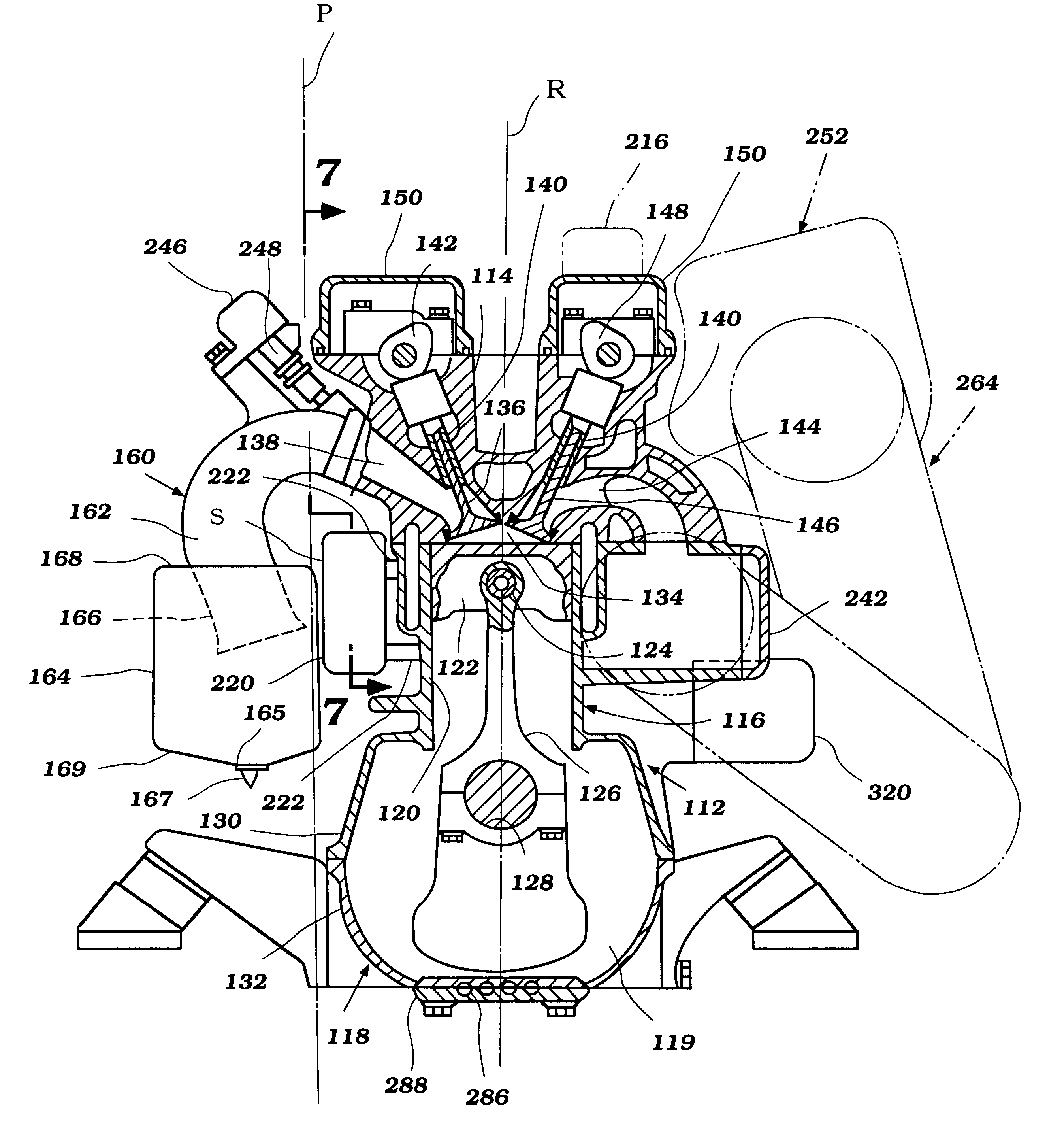
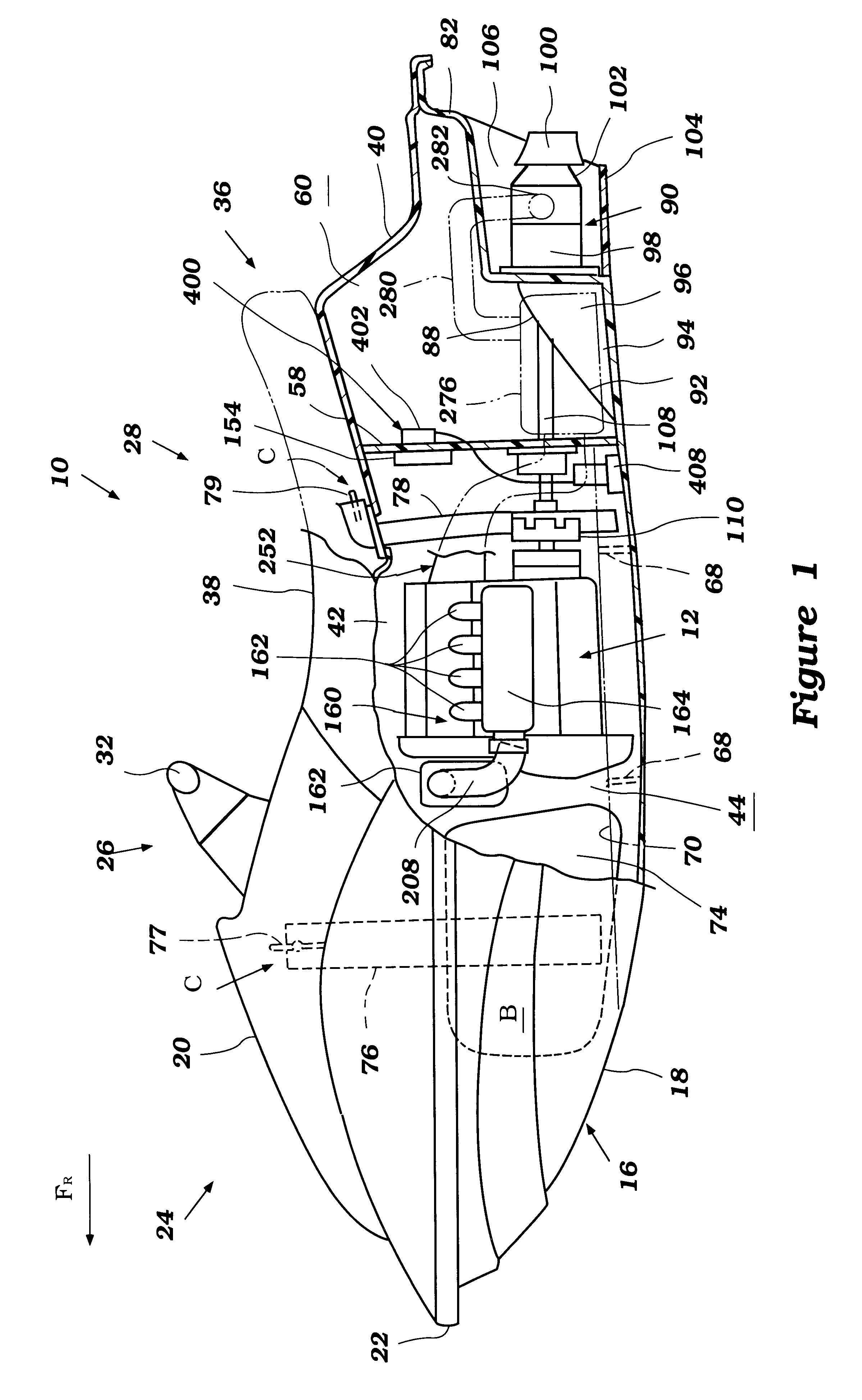
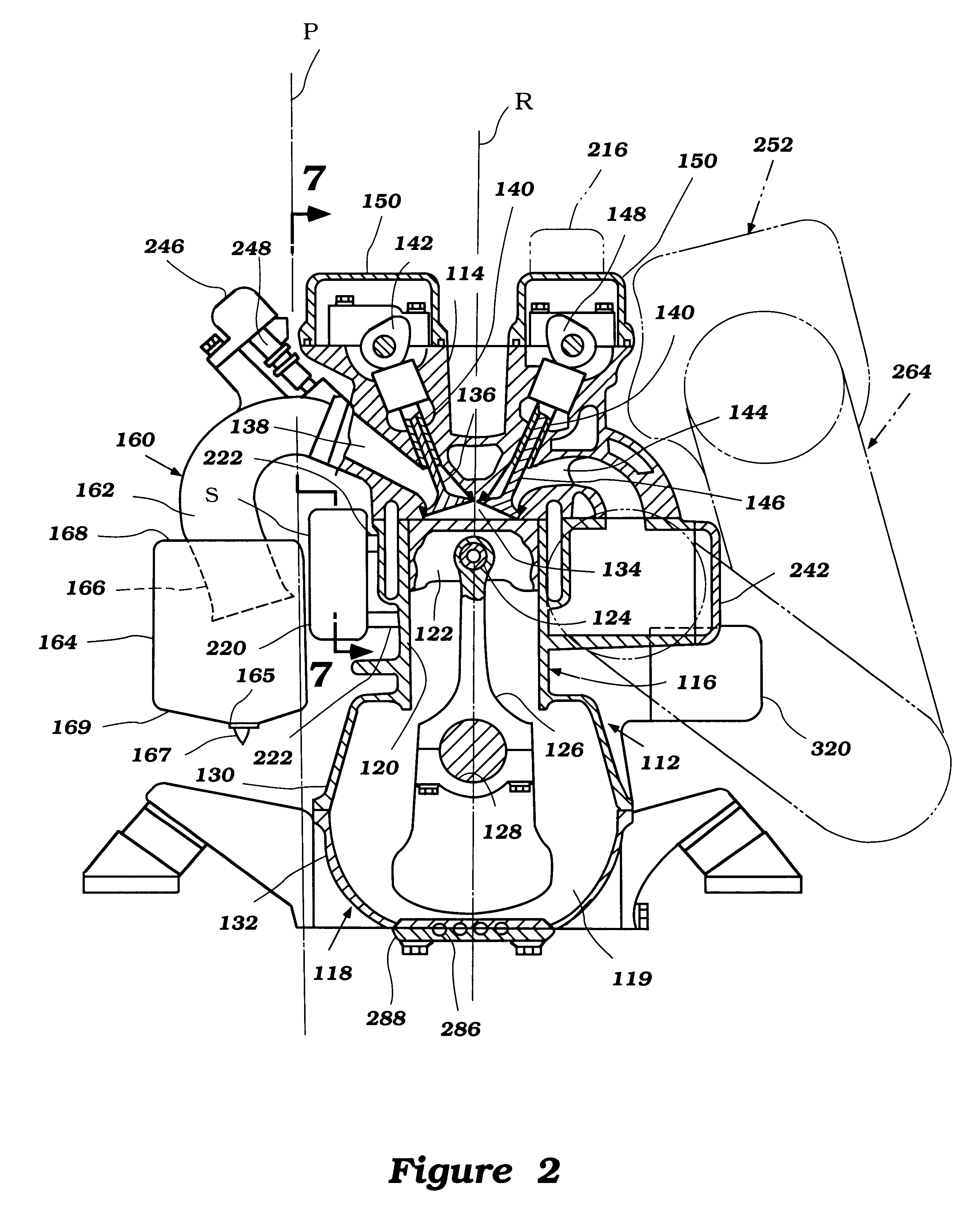
The present invention generally relates to an improved vapor separator arrangement having certain features and advantages in accordance with the present invention. The vapor separator arrangement is described in conjunction with a personal watercraft because this is an application in which the system has particular utility. Accordingly, an exemplary personal watercraft 10 will first be described in general detail to assist the reader's understanding of the environment of use. Of course, those of ordinary skill in the relevant arts will readily appreciate that the vapor separator arrangement described herein can also have utility in a wide variety of other settings, for example, without limitation, small jet boats and the like.

The small watercraft and a corresponding engine 12 used in the small watercraft will be described with initial reference to FIGS. 1 and 18. With reference to FIG. 18, it is apparent that the engine 12 of FIG. 18 is a modified arrangement of the engine 12 of FIG...


PUM


Abstract

A personal watercraft features a hull defining an engine compartment. An engine is mounted within the engine compartment. The engine comprises a cylinder head, a cylinder body and a crankcase. An induction system supplies air to the engine for combustion. The induction system comprising an intake box, an intake silencer, and a set of intake pipes that extend from the intake box to the engine. The intake pipes extend upward and inward toward the engine. A protective chamber is formed by an inside surface of the intake box, an outside surface of the engine and a lower surface of the pipes. A vapor separator is disposed within this protective chamber. The protective chamber can be augmented by an overhanging portion of the cylinder head, a protrusion from the cylinder body or other extensions from the intake box.

Description

PRIORITY INFORMATIONThe present application is based on and claims priority to Japanese Patent Application No. 11-170731, which was filed on Jun. 17, 1999, the entire contents of which are hereby expressly incorporated by reference. The entire contents of Japanese Patent Application No. 11-75968, which was filed on Mar. 19, 1999, are also hereby expressly incorporated by reference.1. Field of the InventionThe present invention generally relates to a control system for a personal watercraft. More particularly, the present invention relates to a emergency shut-off system for a personal watercraft.2. Description of Related ArtAs personal watercraft have become popular, they have become increasingly fast. Today, personal watercrafts are capable of speeds greater than 60 mph. To attain such speeds, personal watercrafts are driven by high power output motors.Typically, two-cycle engines are used in personal watercraft because two-cycle engines have a fairly high power to weight ratio. One...

Claims


Application Information

Patent Timeline
Patent Type & Authority Patents(United States)
IPC IPC(8): B63B35/73B63H21/00B63H21/14F01M13/02F01M13/00F02B61/00F02B61/04F02M35/00F02M35/16B63B39/14B63B39/00B63B43/00F01M1/12F01M1/00B63H21/22F02D17/04F02D33/00F02D41/04F02M37/00F02M37/20
CPCB63B35/731B63H21/14B63H21/22F01M13/022F02B61/045F02D17/04F02D33/006F02D41/042F02M35/10039F02M35/10111F02M35/112F02M35/165F02M35/168F02M37/007B63B39/14B63B43/00B63B2770/00B63H21/24F01M2001/126F02M35/02F02M35/10216F02M37/20B63H21/386B63B34/10
Inventor NANAMI, MASAYOSHI
Owner YAMAHA MOTOR CO LTD
Why Eureka
Try Eureka