Multi-core conductive wire and a method of manufacturing the same

a multi-core conductive wire and manufacturing method technology, applied in the direction of insulated conductors, cables, cable terminations, etc., can solve the problems of fatal increase of resistance, restricted fixing by resistance welders, and insufficient processing of terminal portions of such multi-core conductive wires. achieve high fixing force, high binding force, and high strength

Inactive Publication Date: 2002-09-17
HITACHI LTD +1
View PDF9 Cites 31 Cited by
  • Summary
  • Abstract
  • Description
  • Claims
  • Application Information

AI Technical Summary

Benefits of technology

In the present invention, in order that the multi-core conductive wire has the electric performance, in view of the necessity for the terminal portion to be integrated at first, it is preferable that molding to desired shape be performed in cold processing without thermal damage, and that the terminal portion molded in cold processing be connected substantially to other electric conductor terminal.
FIG. 9B shows an example of connection by a rivet 10 using a fitting 9. The fitting 9 protects a terminal 5 and serves as a connection plate to other terminal platge 7. A hole 6 of the fitting 9 and a hole of the terminal are tightened by the rivet 10 to be fixed. As the material for the rivet 10, Cu, Cu alloy, Al alloy, Fe series or the like can be applied. If the connection is performed in this system, all processings from the molded end portion to the end portion connection are performed in cold treatment, the multi-core conductive wire of the molded end portion structure being excellent in flexibility can be obtained without thermal damage.

Problems solved by technology

As called a multi-core conductive wire, since a large number of wires are used in the conductive wire, a simple method of processing a terminal portion in such a multi-core conductive wire has not been yet established, being in difficulties.
When a large number of multi-core conductive wires are used, the fixing by the resistance welder is restricted.
Therefore the thermal damage of the wires themselves becomes great, resulting in increase of the resistance being fatal as the electric equipment.
Also with the latter, since the plating is applied to the individual wires, the price of the wires themselves becomes expensive.
As a result, it is difficult to process a terminal portion of a multi-core conductive wire with high quality.
When the number of the conductive wires in the terminal portion is in the range of three to a large number (for example, 10,000), and moreover a range of the wire diameter is, for example, from 0.10 mm to 1.5 mm, approximately, it is very difficult that all different conductive wires are fixedly secured together in the method of the prior art.
Sho 55-11327 have problems in that the coupling force between the wires is weak and further the number of the manufacturing processes is much.

Method used


Image

  • Multi-core conductive wire and a method of manufacturing the same
  • Multi-core conductive wire and a method of manufacturing the same
  • Multi-core conductive wire and a method of manufacturing the same

Examples


first embodiment

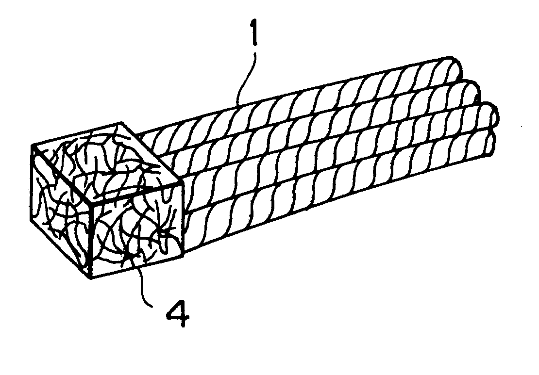
These multi-core conductive stranded wires are subjected to cold pressure-molding using a die used in the That is, the multi-core conductive stranded wires are arranged in the die and molded into a prescribed shape by applying a pressure using a press. The molded article has a shape of 8.2 mm.times.8.1 mm and about 3.2 mm in thickness. In this time, the pressure of the press is about 3 tons.

The fixing force of the molded articles subjected to molding in the embodiments and the comparison example as above described was tested by the peeling-off test. The peeling-off test in the case of the six bundles were divided into the three bundles at the upper stage and the three bundles at the lower stage, and the upper bundles and the lower bundles respectively were grasped by a chuck and pulled by a tension tester. Also in the case of the straight wires, the peeling-off test was performed in that the straight wires were substantially halved, and the respective wires were grasped by a chuck ...

embodiment 6

This embodiment as shown in FIG. 13 is constituted conductive wires 1 being six bundles of stranded wires are obtained as in the first embodiment, and a foil 36 of copper phosphide solder described in the third embodiment is mounted on a terminal 5 of the multi-core conductive wires 1 so that it is brazed to other conductor, is previously molded as a clad on a surface of a copper conductor 38 and the member constituted in this manner is also mounted on a terminal and molded integrally.

FIG. 14 is a sectional view of an electric resistance heater where the copper conductor 38 with the solder foil 37 cladded thereon is joined by brazing with the terminal 5 of the multi-core stranded wires 1. The solder foil 37 is held on and contacted with the terminal 5 between an upper electrode and a lower electrode, and pressure is applied and an alternating current is flowed thereto. As a result, the local heating and melting are produced between the terminal 5 and the solder foil 37 and thereby t...


PUM

PropertyMeasurementUnit
diametersaaaaaaaaaa
diameteraaaaaaaaaa
diameteraaaaaaaaaa

Abstract

An object of the invention is to provide a multi-core conductive wire having the small number of manufacturing processes and a terminal with high strength, and a method of manufacturing the multi-core conductive wire.The multi-core conductive wire is provided with a terminal, at the end portion thereof, where individual strands of the multi-core conductive wire are entangled with each other and the terminal is molded by subjecting to pressure-molding.A method of manufacturing a multi-core conductive wire comprises a step of processing the multi-core conductive wire into a state where individual strands of the multi-core conductive wire are partially entangled with each other; a step of temporarily molding the processed portion; and a step of further applying pressure to the temporarily molded portion for pressure-molding or plastic working.

Description

The present invention relates to a novel multi-core conductive wire to be used for various sorts of electric equipment, and more particularly to a multi-core conductive wire having a novel terminal and its manufacturing method.In the prior art, various methods have been used as a processing method of a terminal portion of a multi-core conductive wire (called conductive wire and multi-core wire) to be used in electric equipment. As called a multi-core conductive wire, since a large number of wires are used in the conductive wire, a simple method of processing a terminal portion in such a multi-core conductive wire has not been yet established, being in difficulties.On the other hand, in the processing of the terminal portion of the multi-core conductive wire, also such technology is demanded that other material wrapping the multi-core conductive wire is not used but the processing can be performed by only the multi-core conductive wire.As a method of processing a terminal portion in ...

Claims


Application Information

Patent Timeline
Patent Type & Authority Patents(United States)
IPC IPC(8): B23K11/11H01B5/00H01R4/02H01B7/00
CPCB23K11/115H01B5/00B23K2201/32B23K2101/32H01R11/12H01R43/0214
Inventor HARAMAKI, TAKASHISAKURAI, IZUMIKOJIMA, YOSHITAKA
Owner HITACHI LTD
Why Eureka
Try Eureka