System and method for temporally controlling instruction execution

a technology of temporally controlling instruction execution and instruction, which is applied in the direction of computation using denominational number representation, generating/distributing signals, instruments, etc., can solve the problems of program event-driven, prior art program execution methods are no longer acceptable, and the execution speed of instructions is limited only by the speed of the underlying hardwar

Inactive Publication Date: 2002-09-17
IBM CORP
View PDF14 Cites 36 Cited by
  • Summary
  • Abstract
  • Description
  • Claims
  • Application Information

AI Technical Summary

Problems solved by technology

Instruction execution speed is limited only by the speed of the underlying hardware.
Often, however, external events may affect program execution or, the program may be event-driven.
However, for applications where those tolerances are such that timing must be within a single microprocessor clock cycle, these prior art program execution methods are no longer acceptable.
In particular, these prior art methods are unsatisfactory, for example when temporal precision is important, such as, for video compression / decompression, where large amounts of data may be stored, transported and displayed.
Consequently, to reduce the video data volume, redundant information is commonly removed from the video, compressing the video data.
Unfortunately, when the redundant information is removed, the temporal characteristic of the video content may be changed with the real-time nature of the video material being lost.
Accordingly, this prior art method is unsuitable for applications where there is no content or where the time of execution must come from a source other than the content, such as when a master clock defines the execution time.
While this prior art method of temporally controlling program execution is suitable for most current applications, it also is relatively inaccurate, and depends upon the time to initialize the timer and to complete the interrupt operation, which may vary significantly.
Furthermore, where precision of a single microprocessor clock cycle is needed, these methods are unacceptable.

Method used


Image

  • System and method for temporally controlling instruction execution
  • System and method for temporally controlling instruction execution
  • System and method for temporally controlling instruction execution

Examples


Embodiment Construction

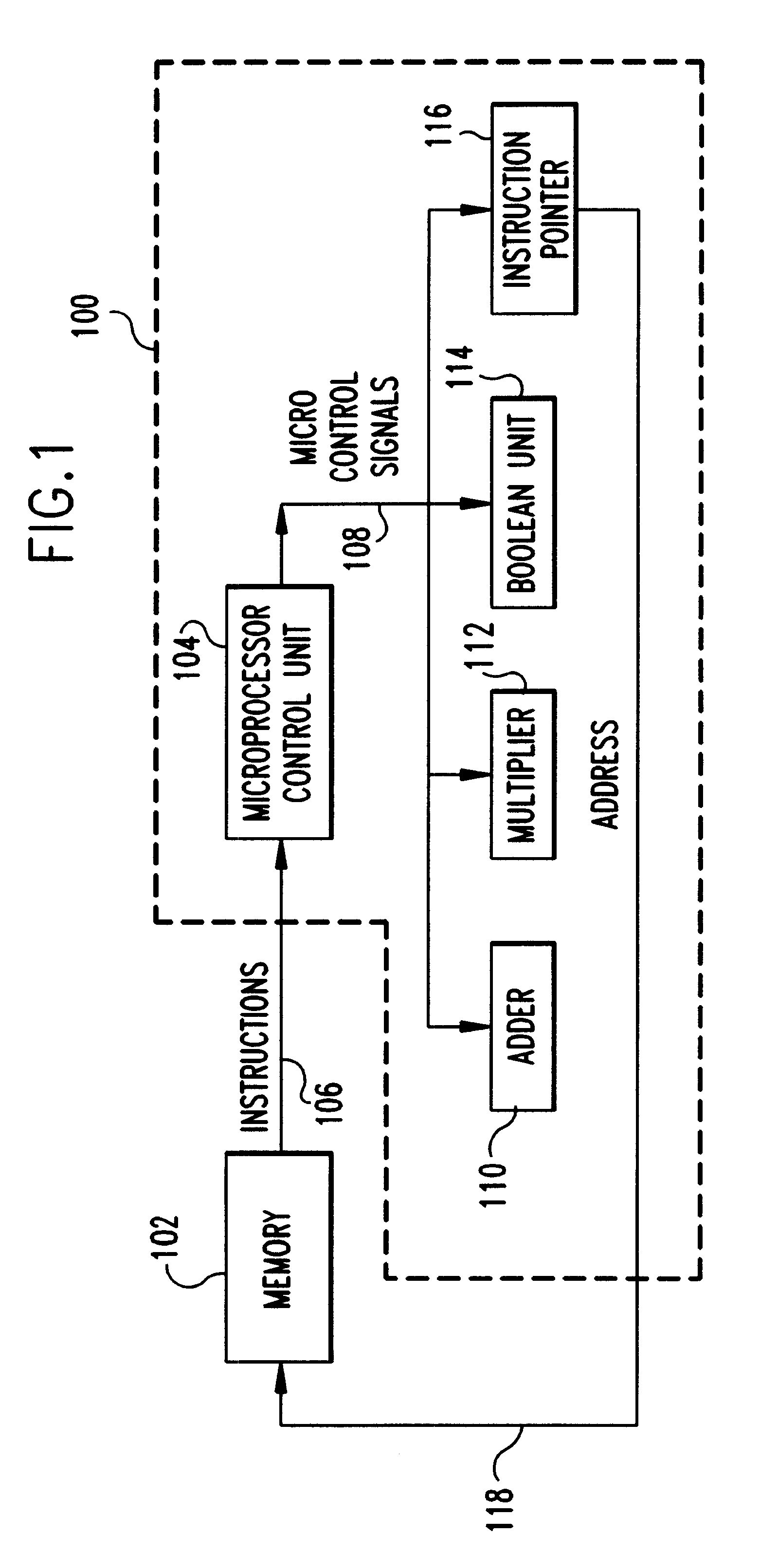
Referring now to the drawings and, more particularly, FIG. 1, a simplified block diagram of a microprocessor 100 and memory 102. A Microprocessor Control Unit (MPCU) 104 fetches instructions from the memory 102 on instruction bus (Ibus) 106. After parsing the instructions, the MPCU 104 generates Micro Control Signals which are passed on Micro Control Signals bus (.mu.CSbus) 108 to various functional units 110, 112, 114 and to Instruction Pointer 116, which provides an address on address bus 118 for the next instruction to be executed.

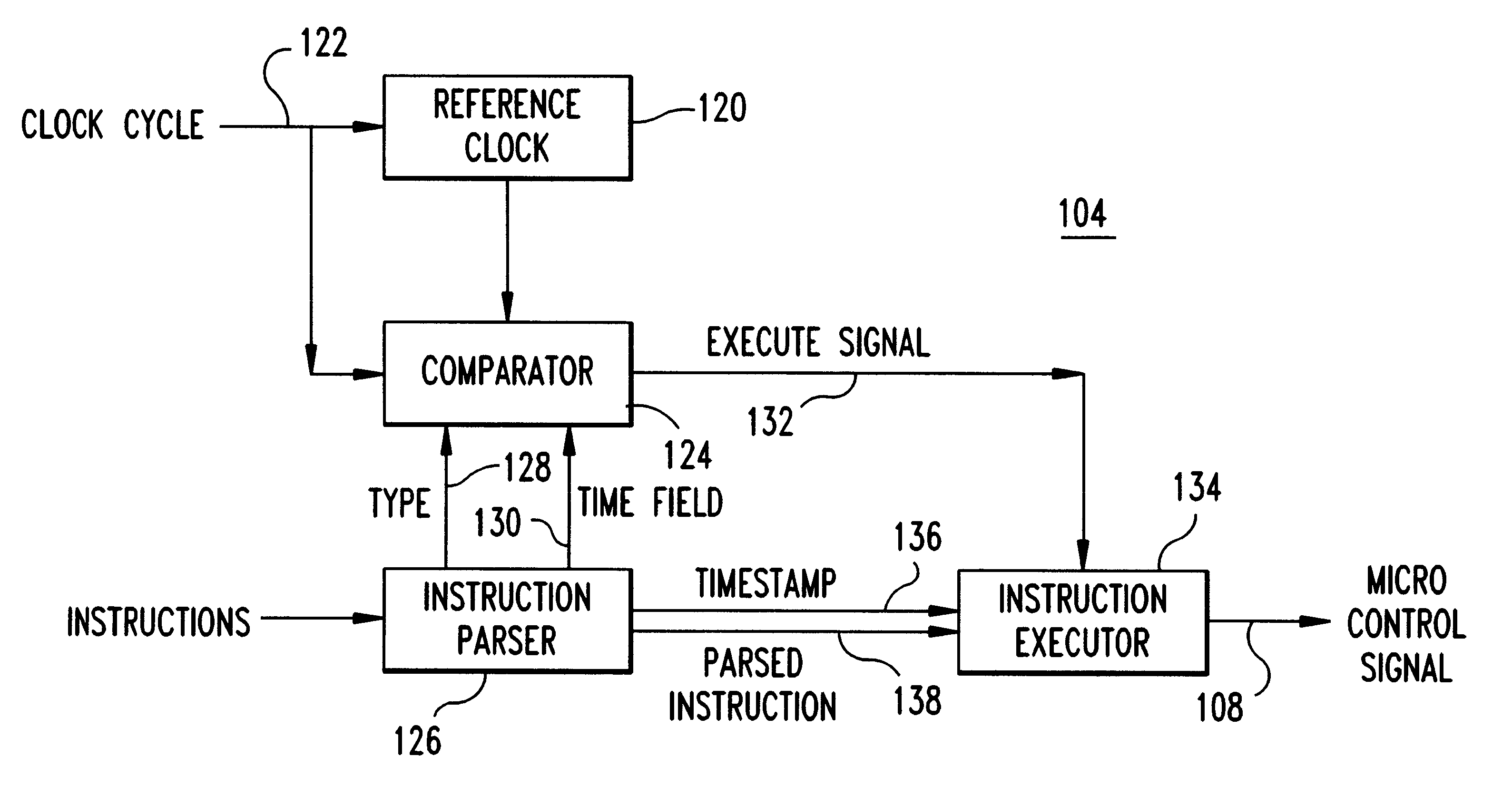
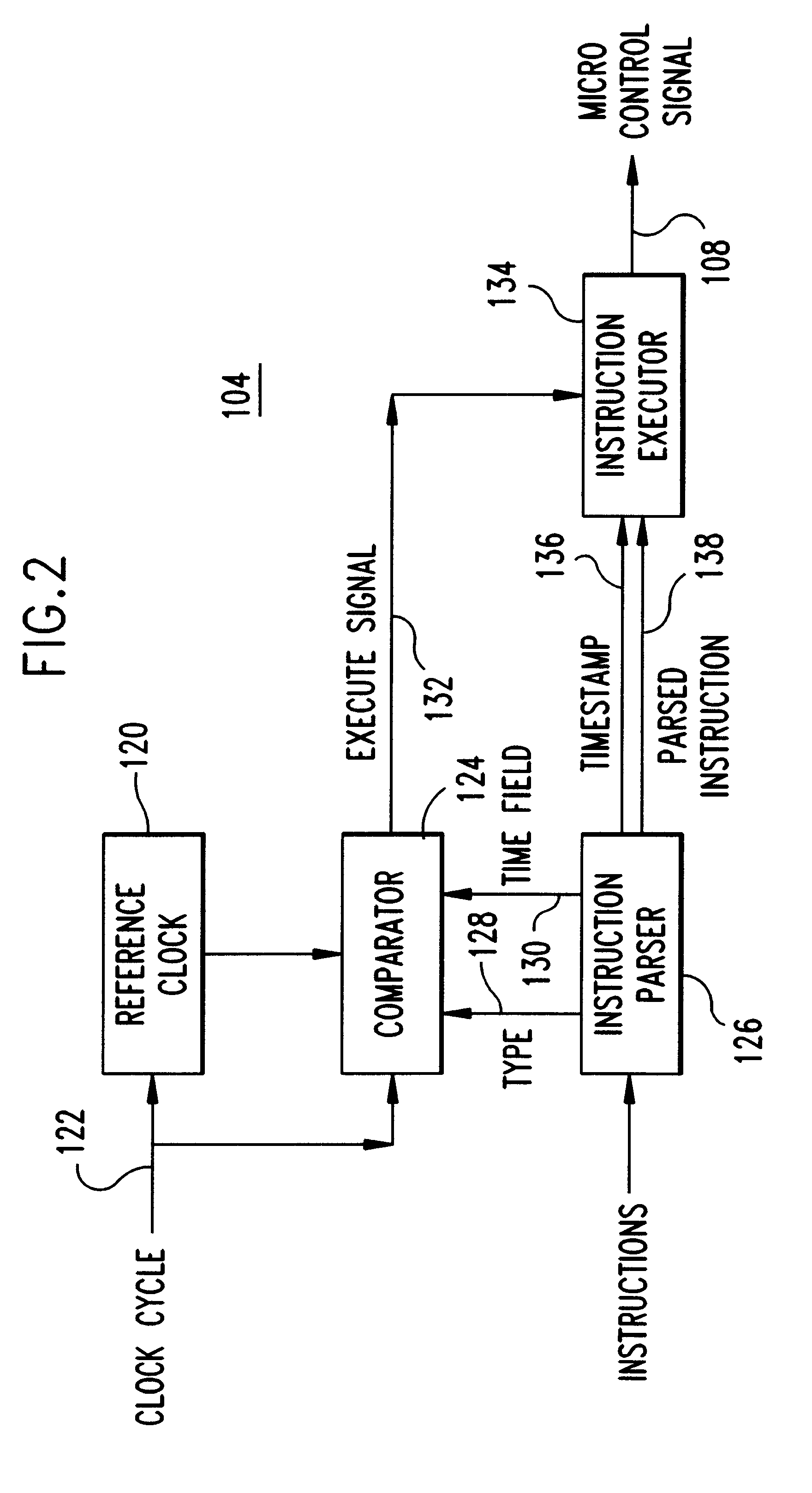
FIG. 2 is a detailed example of a preferred embodiment MPCU 104. Reference Clock counter 120 is a multi-bit counter that increments on every cycle of the master clock provided at Clock Cycle input 122. The Reference Clock counter 120 is initialized at program start. Comparator 124 monitors the Reference Clock counter 120. Instruction Parser 126 parses instructions, stripping off timestamp information from Timestamped Instructions.

When such a timestamped...


PUM


Abstract

An apparatus and method of controlling instruction execution in the apparatus with a precise temporal execution arrangement. The apparatus may be a processor or microprocessor capable of executing a function specific wait state that is dependant upon a type specified by an instruction field. The processor includes a reference clock counter that maintains the wait count, an instruction parser that strips the wait type and count from instructions and passes the stripped information to a comparator. The comparator compares the stripped information against the wait count. The wait types include: a relative timestamp type indicating execution at some time subsequent to the present cycle; a direct timestamp type indicating an absolute time for execution; and a timestamp range indicating a time period when execution is valid.

Description

1. Field of the InventionThe present invention is related to computer processors and, more particularly, to temporally controlling the execution of instructions in a microprocessor or digital signal processor.2. Background DescriptionSo-called superscalar Microprocessors and Digital Signal Processors operate by sequentially executing instructions which specify the individual operations. These sequential operations can include, for example, adding two numbers, subtracting numbers, multiplying numbers, moving data, performing boolean math, etc. A typical program for a microprocessor is, basically, a sequence of instructions written to perform a particular task.Some program instructions may reorder instruction execution sequence on the fly. For example, a short sequence of instructions may be executed repeatedly, or under a given set of conditions a block of instructions may be skipped altogether. Typical instructions to modify the sequence of instructions after execution has begun may...

Claims


Application Information

Patent Timeline
Patent Type & Authority Patents(United States)
IPC IPC(8): G06F9/30G06F9/38
CPCG06F9/30145G06F9/3836G06F9/3855G06F9/3856
Inventor JANNIELLO, JAMES P.
Owner IBM CORP
Why Eureka
Try Eureka