Oil well pipe screw joint, and threading method and apparatus therefor

a technology of oil well pipe and screw joint, which is applied in the direction of screw threaded joints, screw connections, hose connections, etc., can solve the problems of many problems, such as the leakage of fluid (such as natural gas or crude oil) contained therein outside, and damage to corner sections of the tread

Inactive Publication Date: 2002-09-24
KAWASAKI STEEL CORP
View PDF17 Cites 29 Cited by
  • Summary
  • Abstract
  • Description
  • Claims
  • Application Information

AI Technical Summary

Problems solved by technology

In this condition, when tensile forces or bending forces impinge on the tube, the API trapezoidal screw threads are apt to be disengaged, possibly causing a problem in that fluid (such as natural gas or crude oil) containing therein leaks outside.
This causes damage to corner sections of the treads, which is a cause of leakage of gas or liquid.
To practically use the negative screw threads, however, many problems still remain.
One of the problems relates to the thread-machining technique.
Furthermore, when the joints produced as described above are used, deformations of a flank face 16 are apt to occur, and the joints are therefore moved by forces, particularly, compression forces and tensile forces, thereby producing a problem in that the joints frequently leak fluid.

Method used


Image

  • Oil well pipe screw joint, and threading method and apparatus therefor
  • Oil well pipe screw joint, and threading method and apparatus therefor
  • Oil well pipe screw joint, and threading method and apparatus therefor

Examples


example 2

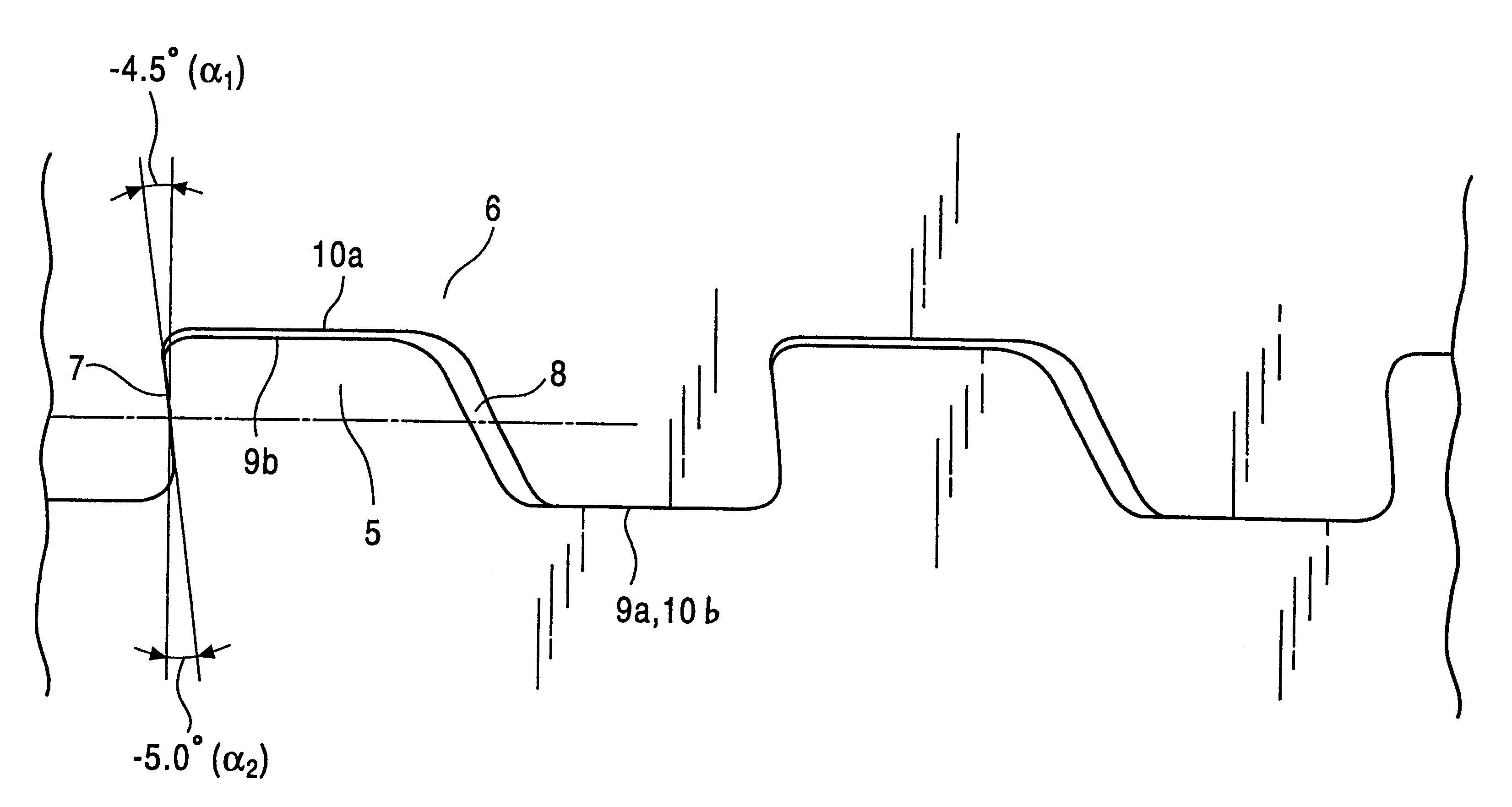
For the tubular body 13, threaded-joint-forming pipes of 13-Cr steel and of various outside diameters were used, and female screw threads as described above were formed therein. The negative-value range of flank angles 15 was from -0.5.degree. to -25.degree.. At this time, the thread-machining method and the thread-machining apparatus of the present invention were applied, and in addition, threading-machining was carried out by using the conventional thread-machining apparatus described in the Related Art above. A rotational body in this case was fed at a rate of 5.08 mm per rotation.

As a result of the above applications of the thread-machining method and the thread-machining apparatus of the present invention, threads can be cut so as to be smooth by only one-pass feeding of the tubular body 13 into the apparatus, and threads of high quality can therefore be cut without uneven pitches being produced. Also, thread-machining time for the joints of any of the diameters can be reduced ...


PUM

PropertyMeasurementUnit
load flank angleaaaaaaaaaa
stubbing flank angleaaaaaaaaaa

Abstract

An oil-country-tubular threaded joint can withstand tensile forces, and in addition, other forces such as compression and bending forces, thus producing highly improved characteristics in regard to the prevention of fluid leakage. The oil-country-tubular threaded joint is formed of male screw threads and female screw threads which have a load face whose load flank angles are in a range of -3° to -25°, in which the load flank angles are varied at a position at which the load face is divided in the height direction of the male screw thread into an upper side and a lower side so that an upper load flank angle is smaller than a lower load flank angle by 0.5° to 2.0°. Also, a thread-machining apparatus for the oil-country-tubular threaded joint uses chasers having cutting edges which are shaped so as to correspond to thread shapes for machining screw threads whose flank angles are partly of negative values for the oil-country-tubular threaded joint. In the apparatus, the cutting edges which are to be used from the beginning to the end of thread-machining are arranged on the individual chasers sequentially according to the shape, and the chasers are on one rotational body so as to machine screw threads at a rate of one pitch per rotation of the rotational body. This allows negative screw threads of quality higher than in conventional cases to be cut in a reduced time.

Description

The present invention relates to an oil-country-tubular threaded joint, particularly, to an oil-country-tubular threaded joint having highly improved characteristics in regard to the prevention of fluid leakage even in an environment where various forces such as external pressure, tensile forces, compression forces, and bending stresses are exerted thereon. The present invention also relates to a thread-machining method for the oil-country-tubular threaded joint and to a thread-machining apparatus therefor; particularly, the invention relates to a technique of machining and quickly completing female screw threads in the oil-country-tubular threaded joint by using a tool-rotating thread-machining apparatus.BACKGROUND OF THE TECHNIQUESPresently, threaded joints are widely used as in techniques for coupling oil-country-tubulars used for research and production relating to natural resources, such as natural gas and crude oil, at depth of thousands of meters. Oil-country-tubulars (which ...

Claims


Application Information

Patent Timeline
Patent Type & Authority Patents(United States)
IPC IPC(8): B23G1/00B23G1/32B23G1/22F16L15/00F16L15/06
CPCB23G1/22B23G1/32F16L15/001
Inventor YAMAGUCHI, MASAO
Owner KAWASAKI STEEL CORP
Why Eureka
Try Eureka