Hall effect seat switch

a seat switch and seat technology, applied in the field of seat switches, can solve problems such as serious injuries to operators

Inactive Publication Date: 2002-10-01
DELTA SYST
View PDF19 Cites 92 Cited by
  • Summary
  • Abstract
  • Description
  • Claims
  • Application Information

AI Technical Summary

Benefits of technology

FIG. 3A is a top view of a Hall effect seat switch frame;
FIG. 3B is a bottom view of a Hall effect seat switch frame;
FIG. 3C is a perspective view of a Hall effect seat switch frame;
FIG. 4A is a schematic representation of

Problems solved by technology

If the vehicle is running and the operator steps off the vehicle

Method used


Image

  • Hall effect seat switch
  • Hall effect seat switch
  • Hall effect seat switch

Examples


Embodiment Construction

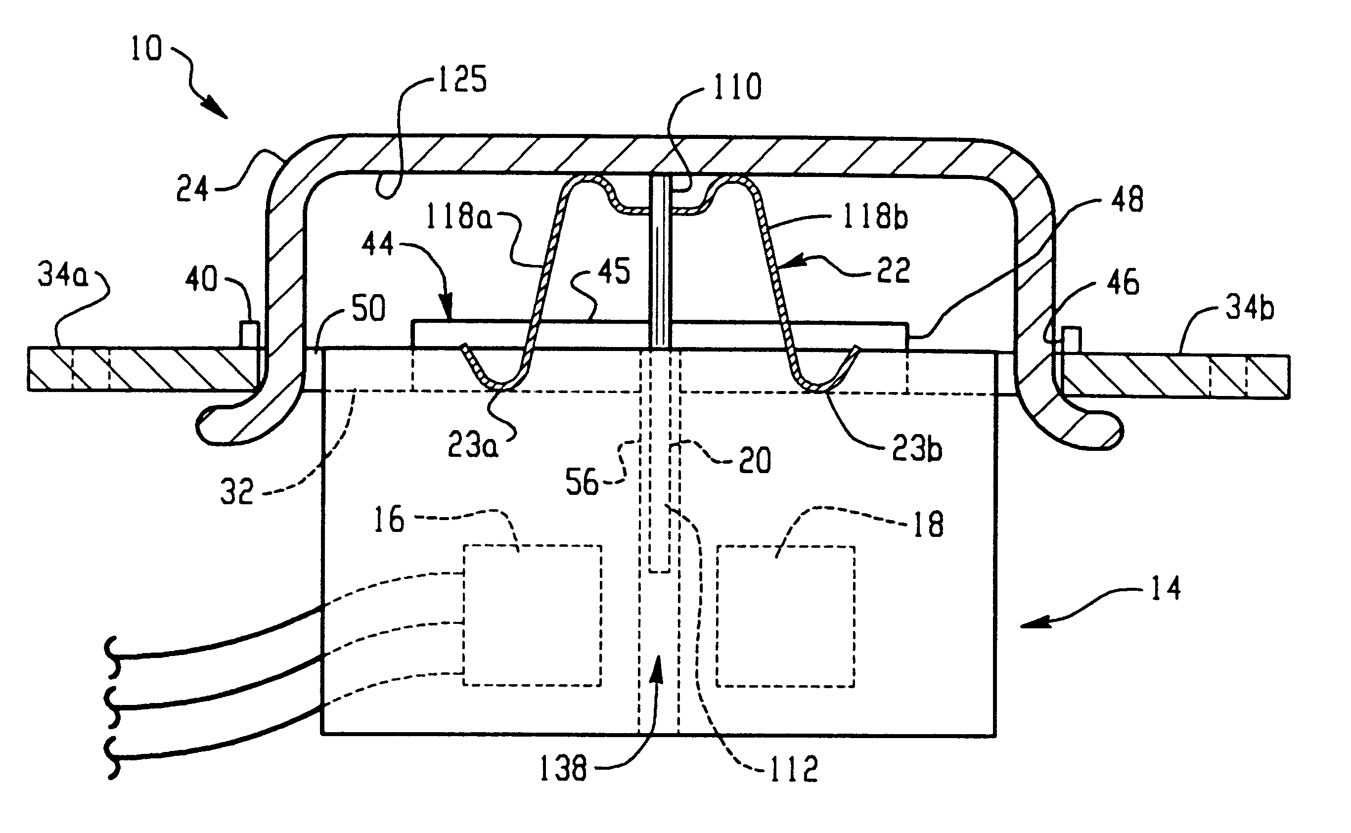
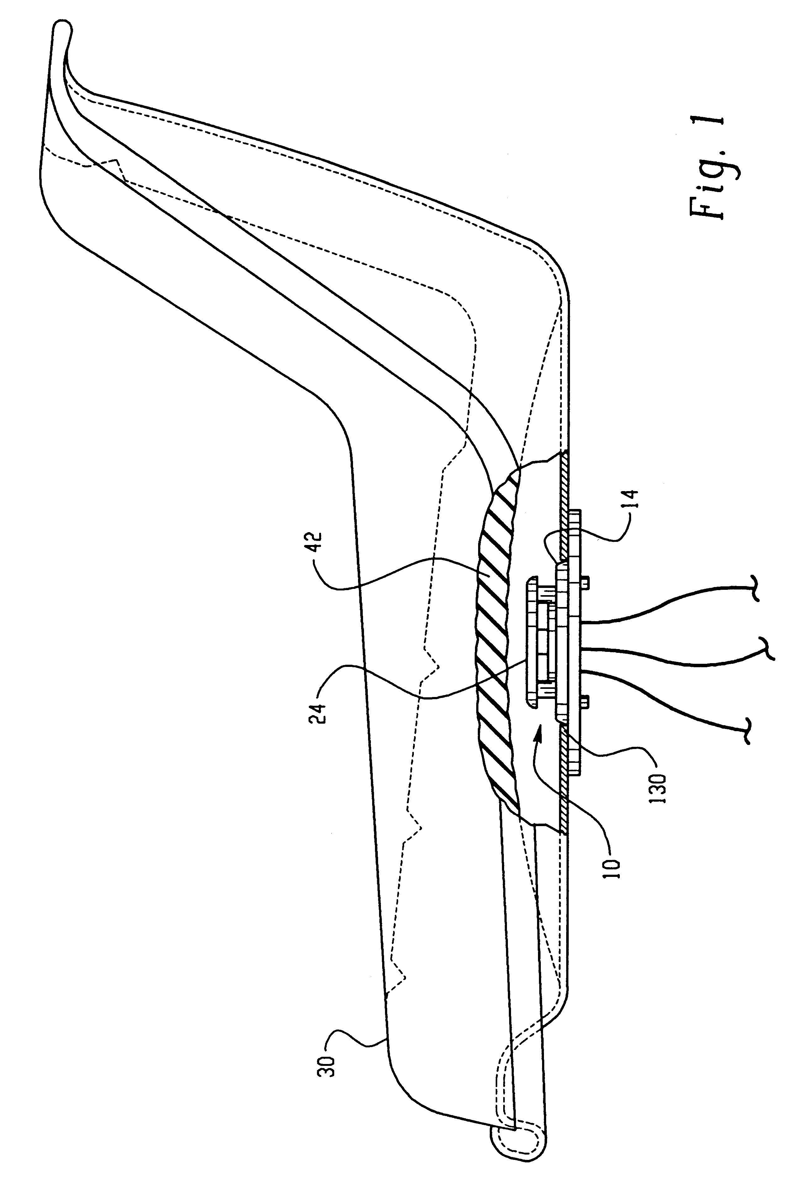
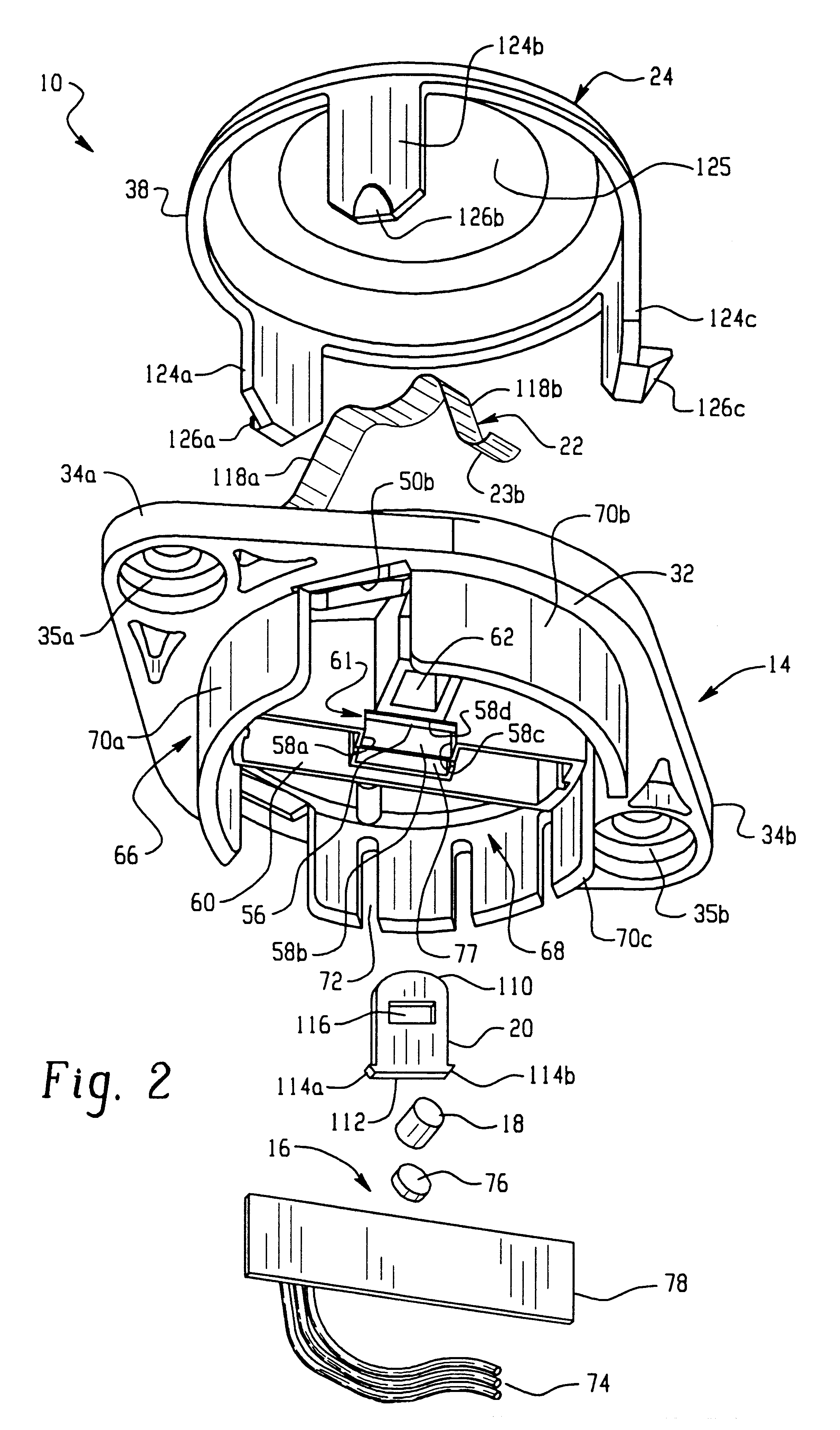
The present invention is directed to a seat switch assembly 10 for controlling operation of a vehicle engine. The seat switch includes a switch frame 14, a Hall effect sensor 16 (FIGS. 4A & 4B), a magnet 18, a vane 20, a spring 22 and a cap 24. The switch frame is constructed so that it can easily be coupled to a vehicle seat 30. The Hall effect sensor 16 is mounted in the switch frame. A magnet 18 is also mounted in the switch frame 14 in a spaced apart relationship with the Hall effect sensor 16. The magnet 18 sets up an associated magnetic field that is communicated to the Hall effect sensor 16 when no obstructions are between the Hall effect sensor and the magnet.

The vane 20 (FIG. 2) is connected to the seat switch frame 14 in such a manner that is free to move. The vane 20 may be moved from a first position that allows the magnetic field to pass from the magnet 18 to the Hall effect sensor 16 to a second position, between the magnet and the Hall effect sensor, which prevents th...


PUM


Abstract

A Hall effect safety switch assembly for de-activating a motor vehicle if a user is not positioned on a vehicle seat. The assembly includes a switch frame for mounting the assembly, a magnet and a hall effect sensor mounted to the switch frame in a spaced apart relationship, and a vane that moves in response to the presence of a vehicle operator on the seat that causes the Hall effect sensor to provide an inhibit signal that prevents an engine from running.

Description

The present invention relates to a seat switch for use in a vehicle and, more particularly, the present invention relates to a seat switch that senses the presence of an operator in a vehicle.It is common in the prior art to equip a vehicle with a seat switch that allows the operator's presence on the seat to be monitored. If the vehicle is running and the operator steps off the vehicle, there is a danger that the operator will be seriously injured. To reduce the hazard of such serious accidents, electrical circuits are used to disable the engine if the operator steps or falls from the vehicle. One example of such a circuit is found in U.S. Pat. No. 5,190,019 to Harvey, which issued on Mar. 2, 1993. The '019 Harvey patent is assigned to the assignee of the present invention. The '019 Harvey patent discloses a seat switch that in combination with other switches forms a circuit that disables a magneto energized spark plug on a lawn or garden tractor to shut down an engine. The disclos...

Claims


Application Information

Patent Timeline
IPC IPC(8): B60N2/00B60K28/00B60K28/04H03K17/94H03K17/95
CPCB60K28/04B60N2/002H03K17/9517
Inventor MICHAUD, JAN L.HARVEY, ARTHUR J.
Owner DELTA SYST
Why Eureka
Try Eureka