Drive of a wafer stepper

a technology of wafer stepper and drive shaft, which is applied in the direction of microlithography exposure apparatus, printers, instruments, etc., can solve the problems of poor capability of position resolution of the motor, insufficient total travel range characteristic, and inability to meet the needs of future semiconductor and precision engineering industries

Inactive Publication Date: 2002-10-01
NAT SCI COUNCIL
View PDF9 Cites 35 Cited by
  • Summary
  • Abstract
  • Description
  • Claims
  • Application Information

AI Technical Summary

Benefits of technology

Another object of this invention is to provide the piezoelectric stage, which is single degree of freedom(Z-axis) and high translation resolution.
An object of the invention is to provide a 2-D(X-Y) translation stage, which is in the long travel range and with high resolution.

Problems solved by technology

With these instruments, precision is enough, but characteristic of a position for total travel range is insufficient.
This incapability will not satisfy the needs of future the semiconductor and precision engineering industries.
A problem is that the capability of the position resolution of the motor is worse than the piezoelectric material, which can generate cumulating error at over-slewing angle.

Method used


Image

  • Drive of a wafer stepper
  • Drive of a wafer stepper
  • Drive of a wafer stepper

Examples


Embodiment Construction

In describing preferred embodiment of the present invention illustrated in the drawings, specific terminology is employed for the sake of clarity. However, the invention is not intended to be limited to the specific terminology so selected, and it is to be understood that each specific element includes all technical and functional equivalents which operate in a similar manner to accomplish a similar purpose. It is also important to note that like parts are referenced by the same reference numeral throughout.

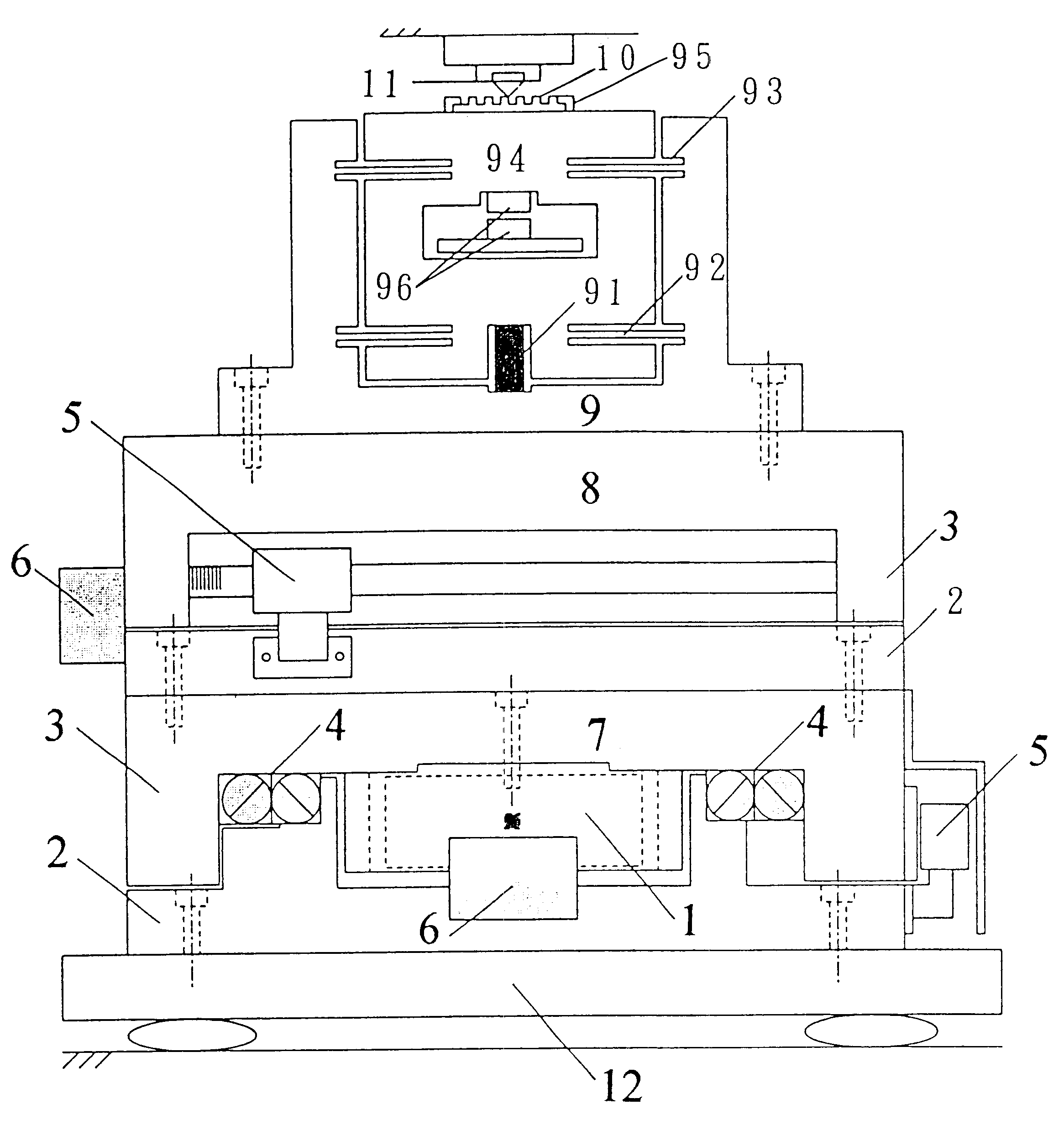
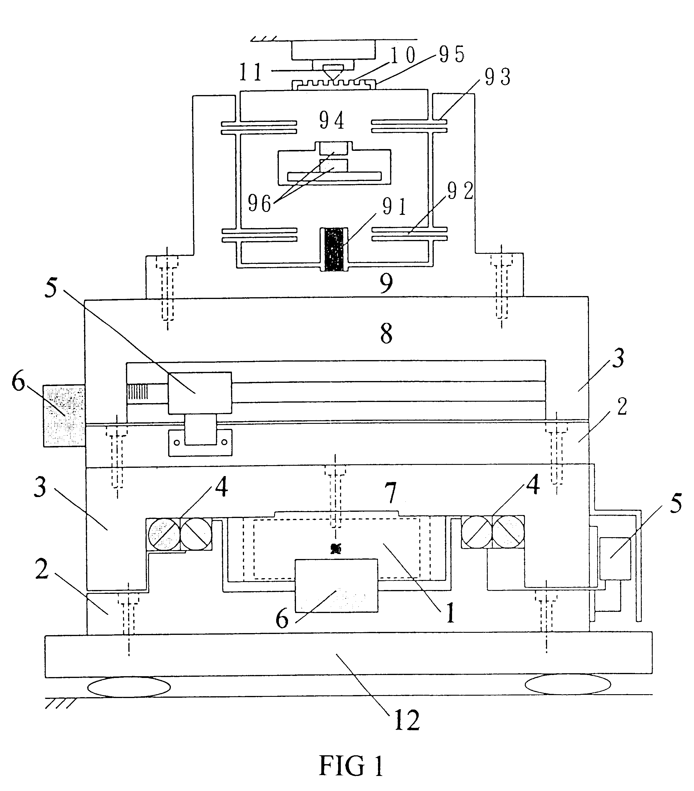
Piezoelectric ceramic of an accumulating layer is used as a translation driver with general reference to FIG. 1. A 2-D (X-Y axis) translation stage utilizing the frictional stick-slip effect and inertia force can be designed and fabricated to achieve ultra high resolution and long travel range. Additionally, basing upon the principle of elastic deformation, a high resolution piezoelectric-driven micropositioner (Z-axis) is designed and fabricated. Moreover, a CD pick-up head, whi...


PUM

PropertyMeasurementUnit
diameteraaaaaaaaaa
diameteraaaaaaaaaa
depthaaaaaaaaaa

Abstract

A piezoelectric-driven 2-D stage (X-Y axis) utilizing the frictional stick-slip effect and inertia force can be designed and fabricated to achieve ultra high resolution and long travel range. Based upon the principle of elastic deformation, a high resolution piezoelectric-driven micropositioner (Z-axis) is designed and fabricated. Moreover, a CD pick-up head and analog linear controller are integrated with Z-axis micropositioner to be a autofocus system. This design is based upon the requirement of the optical lithography developments by using 193 nm Excimer Laser. During this special lighography process, Z-axis micropositioner is needed for the laser beam focusing. A 2-D X-Y stepper is also needed for the movement of the wafer under laser exposure. The wafer stepper is based on the step-repeat and step-scan process.

Description

1. Field of The InventionThis invention is directed to a 2-D (X-Y axis) translation stage, which has a long travel range and high resolution. Moreover, a CD pick-up head, which is a low cost optical probe, is integrated with a Z-axis piezoelectric stage and an analog linear controller to be an optical autofocus system.2. The Prior ArtAlong with unremittingly progress of the precision engineering, in spite of the semiconductor industry, precision machinery industry, biological cell realm, optoelectronic system, microscopic organism, surface engineering, STM, SPM etc all make headway for microminaturization and precision. The needs of a micro or sub-micro position system are growing in number day by day, now there are already many precision position instruments in the industry field.High-resolution position apparatus, constituting the drive of wafer stepper, is the most important item. However, there are already many precision position instruments or equipment in the industry at the p...

Claims


Application Information

Patent Timeline
Patent Type & Authority Patents(United States)
IPC IPC(8): G03F7/20G03B27/58
CPCG03B27/58G03F7/70691
Inventor CHANG, SHUO HUNGLI, S. S.
Owner NAT SCI COUNCIL
Why Eureka
Try Eureka