
Method of manufacturing a profile member of a hybrid composite material

a technology of hybrid composite materials and profile members, which is applied in the direction of manufacturing tools, wood veneer joining, synthetic resin layered products, etc., can solve the problems of limited application of such methods for fabricating profile members for aircraft construction, and not suitable for all possible uses or purposes

Inactive Publication Date: 2002-10-08
AIRBUS OPERATIONS GMBH +1
View PDF25 Cites 36 Cited by
  • Summary
  • Abstract
  • Description
  • Claims
  • Application Information

AI Technical Summary

Problems solved by technology

The forming capabilities of such forming processes are limited in that they are able to achieve only relatively large radii of curvature by an plastic deformation of the laminated stack of hybrid materials.
For that reason, the use of such methods for fabricating profile members for aircraft construction has found only limited application, and is not suitable for all possible uses or purposes in the construction of an aircraft.
It is very difficult to predetermine and thus correct for, or to otherwise avoid, such contour deviations from the desired configuration, which result from the spring-back phenomenon.
For this reason, it is extremely difficult to achieve a required finished contour with high precision using the conventional techniques.
It has further been found that the several laminated layers of the hybrid stack suffer undesired delamination as a result of the deformation process.
Thus, the deformation process must be strictly limited, monitored, and controlled, or else such delamination will readily occur.
This leads to rather high tooling costs, fabrication effort, and fabrication costs.
Also, such a method is only able to achieve contoured profiles having relatively large radii of curvature, similarly to the above described method.

Method used


Image

  • Method of manufacturing a profile member of a hybrid composite material
  • Method of manufacturing a profile member of a hybrid composite material

Examples


Embodiment Construction

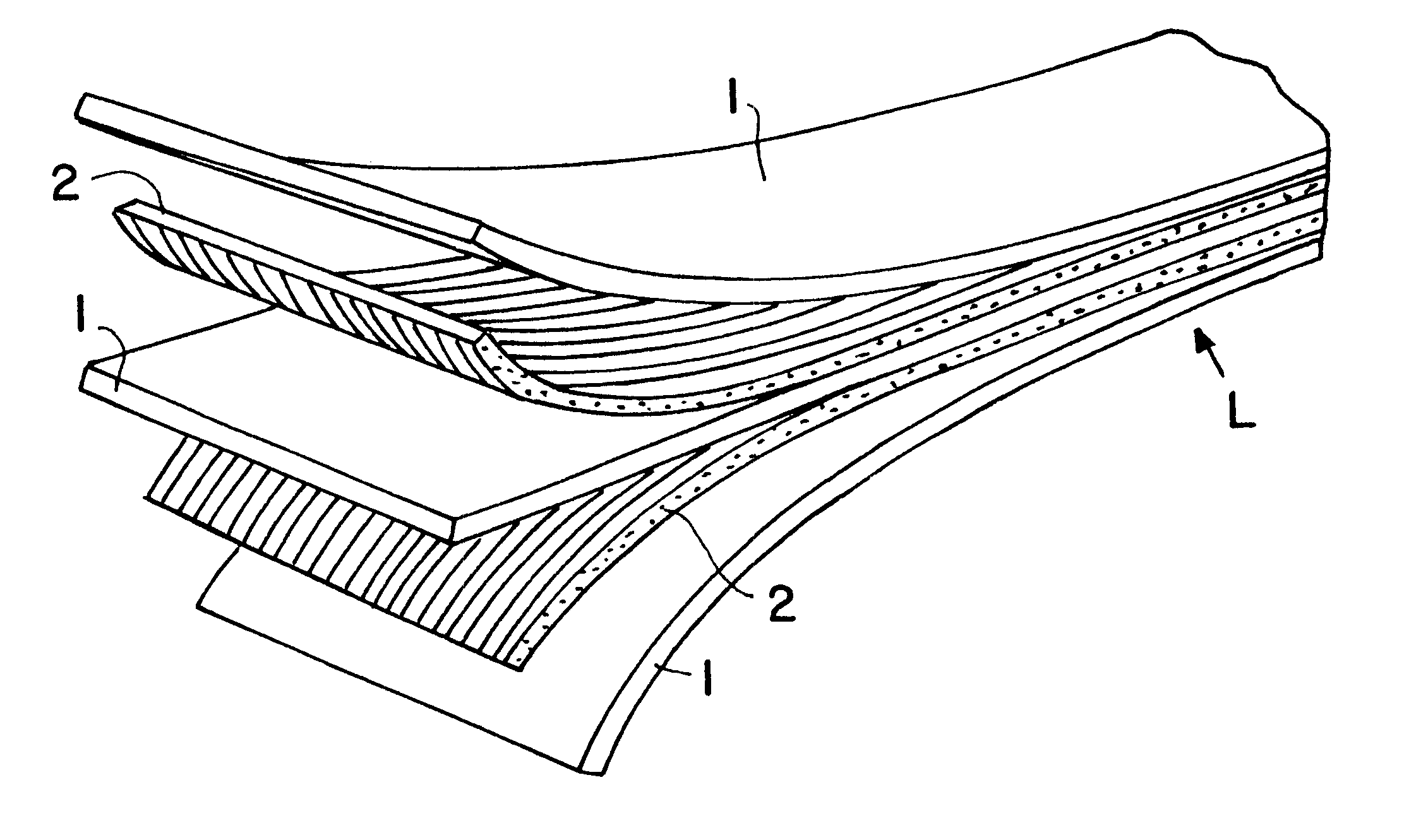
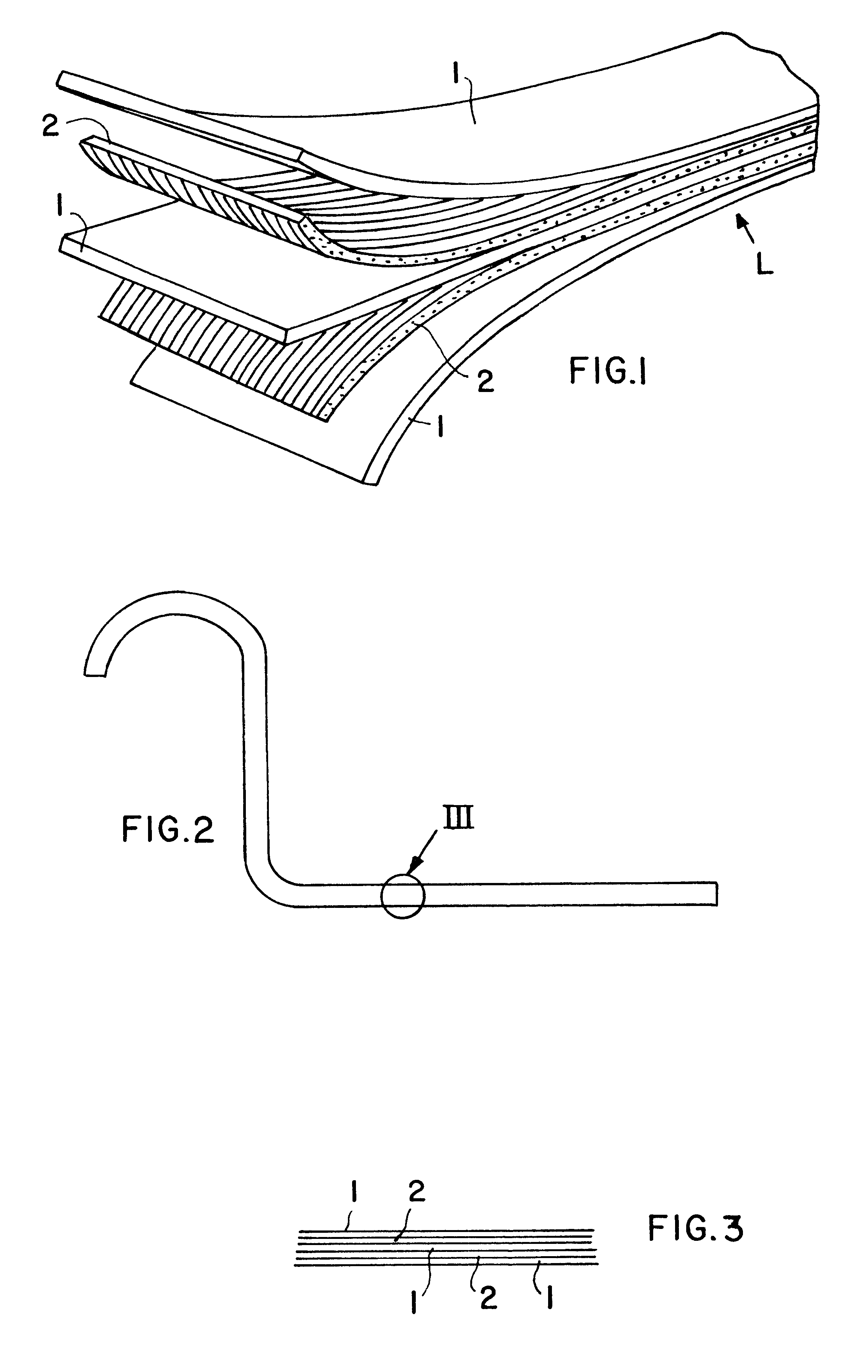
The initial layer structure L shown in FIG. 1 comprises plural precut blanks in the form of metal strips 1 and composite prepreg strips 2, which are alternately stacked, one on another, to essentially any desired number to form the layer structure L having the required thickness and other characteristics. Each of the precut blanks has been prepared in prior processing steps, for example cleaning the metal material, pre-impregnating the fiber-reinforced composite material, and cutting the respective materials into the required dimensions of an elongated strip shape. The metal strips 1 can be fabricated from any appropriate metal material, such as sheet metal of aluminum alloys or titanium alloys, as appropriate for the desired end utilization. The prepreg strips 2 are fabricated from a fiber-reinforced composite material including reinforcing fibers, such as carbon fibers, graphite fibers, glass fibers, aramid fibers or other fibers impregnated with a suitable resin or other thermall...


PUM

PropertyMeasurementUnit
pressureaaaaaaaaaa
temperatureaaaaaaaaaa

Abstract

A profile member of hybrid composite materials including alternating layers of metal and fiber-reinforced composite is fabricated by three successive steps. In a first step, wet composite prepreg layers impregnated with a binder are alternately stacked with metal layers, so that the uncured binder wets the surfaces of the metal layers. Next, the initial uncured layer structure is plastically deformed using successive pressure or bending deformation steps until a prescribed cross-sectional contour of the layer structure is achieved. Finally, the formed layer structure is supported and fixed in an autoclave, in which the binder is cured under an applied mechanical pressure and elevated temperature, to form the finished profile member.

Description

PRIORITY CLAIMThis application is based on and claims the priority under 35 U.S.C. .sctn.119 of German Patent Application 199 56 394.2, filed on Nov. 24, 1999, the entire disclosure of which is incorporated herein by reference.The invention relates to a method of manufacturing a shaped profile member of a hybrid composite material including a stack of alternating metal layers and fiber-reinforced composite layers.BACKGROUND INFORMATIONVarious methods of manufacturing profile members of a hybrid composite material including fiber-reinforced plastic composites and metals are generally known. Typically, such methods involve forming a stack of alternating layers of fiber-reinforced composite material and of metal sheets in a planar configuration and then curing or hardening the composite material layers in the flat planar configuration. After the flat planar stack of material has been cured and hardened, conventional forming processes are used to reform the flat planar hybrid stack into...

Claims


Application Information

Patent Timeline
Patent Type & Authority Patents(United States)
IPC IPC(8): B29C70/04B29C70/08B29C70/00B29C70/88B32B5/26B32B5/22B29C70/34B32B15/08
CPCB29C70/088B29C70/34B32B5/26B29C70/885Y10T29/49906Y10T156/1044B32B15/14B32B1/00B32B2250/42
Inventor KIELIES, ANDREASBECK, ROLFDOEHLE, GUENTER
Owner AIRBUS OPERATIONS GMBH
Features
  • Generate Ideas
  • Intellectual Property
  • Life Sciences
  • Materials
  • Tech Scout
  • Unparalleled Data Quality
  • Higher Quality Content
  • 60% Fewer Hallucinations
Learn More