Medical device with three dimensional collapsible basket structure

Inactive Publication Date: 2002-10-08
EP TECH
View PDF51 Cites 183 Cited by
  • Summary
  • Abstract
  • Description
  • Claims
  • Application Information

AI Technical Summary

Benefits of technology

In a preferred embodiment, the slot hub does not project appreciably beyond the envelope of the structure. The hub lies essentially within the plane of the distal surface to present a surface essentially free of major p

Problems solved by technology

Still, widespread practice of endocardial mapping techniques has been hindered by the difficulties of making suitable endocardial electrode support structures, including severe size constraints, strength and durability demands, and the sheer complexities of fabrication.
While prior multiple electrode support structures may attempt to provided t

Method used


Image

  • Medical device with three dimensional collapsible basket structure
  • Medical device with three dimensional collapsible basket structure
  • Medical device with three dimensional collapsible basket structure

Examples


Embodiment Construction

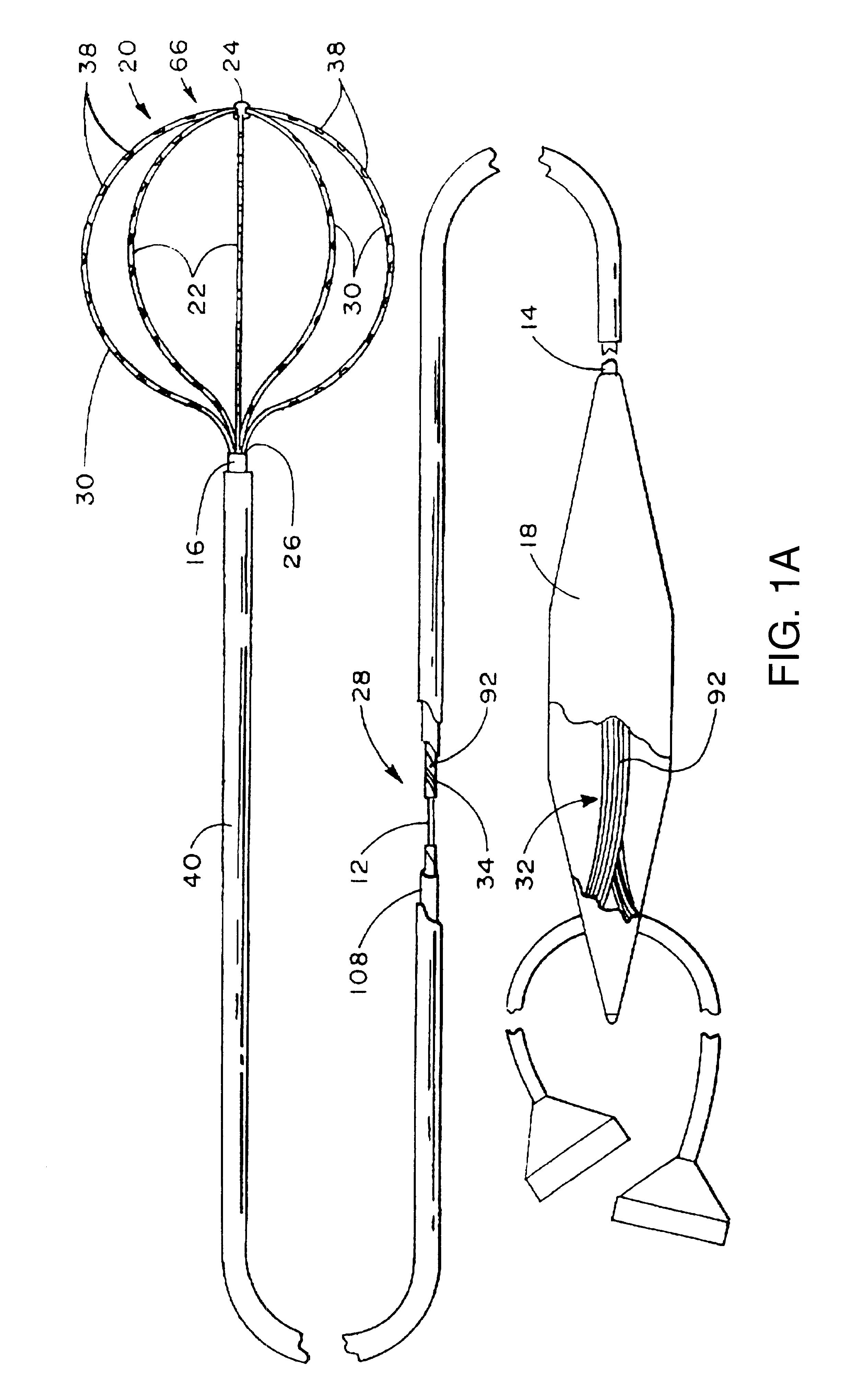
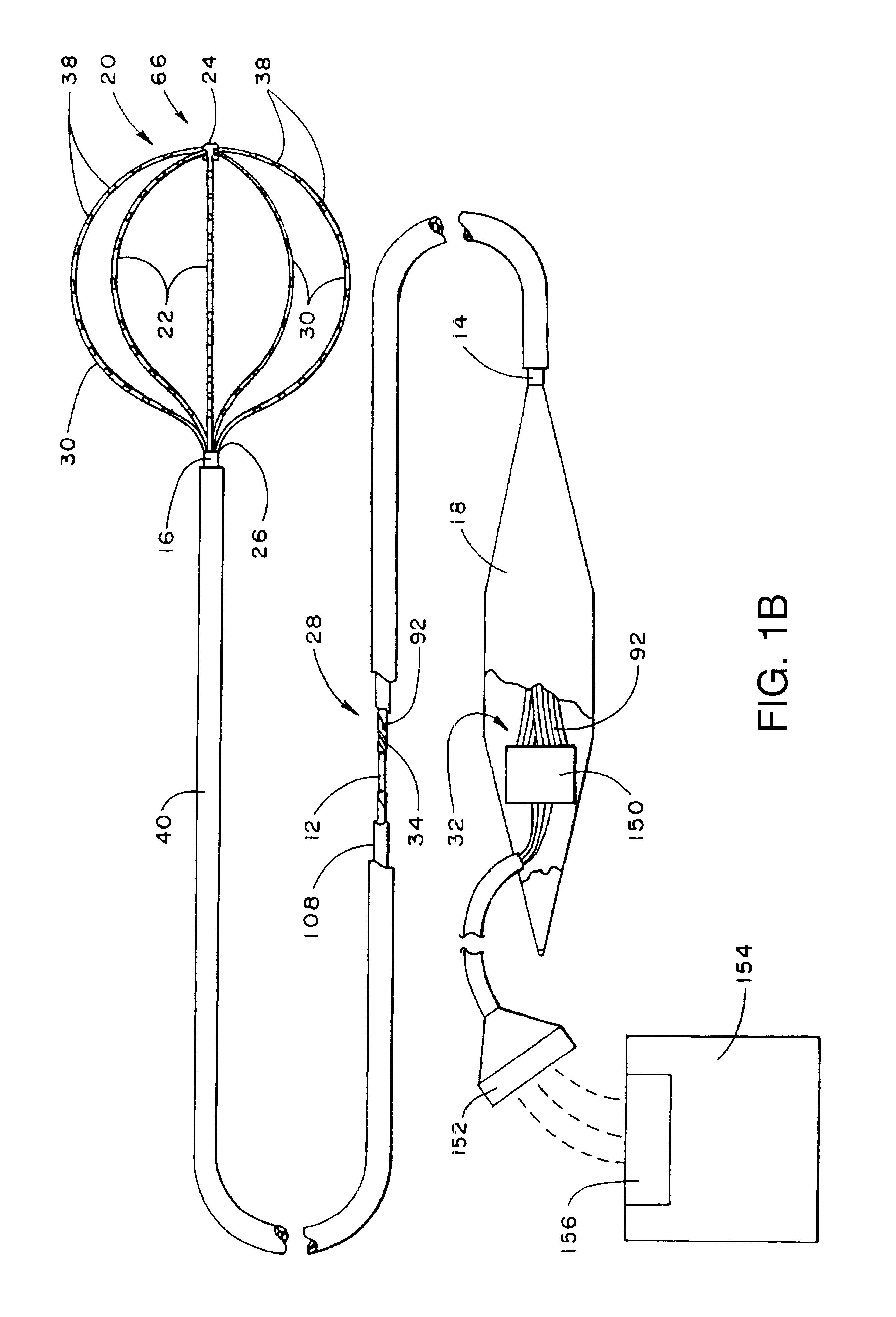
FIG. 1A shows a multiple electrode probe 10 that embodies the features of the invention.

The probe 10 includes a flexible catheter tube 12 with a proximal end 14 and a distal end 16. The proximal end 14 carries an attached handle 18. The distal end 16 carries an electrode support assembly 20.

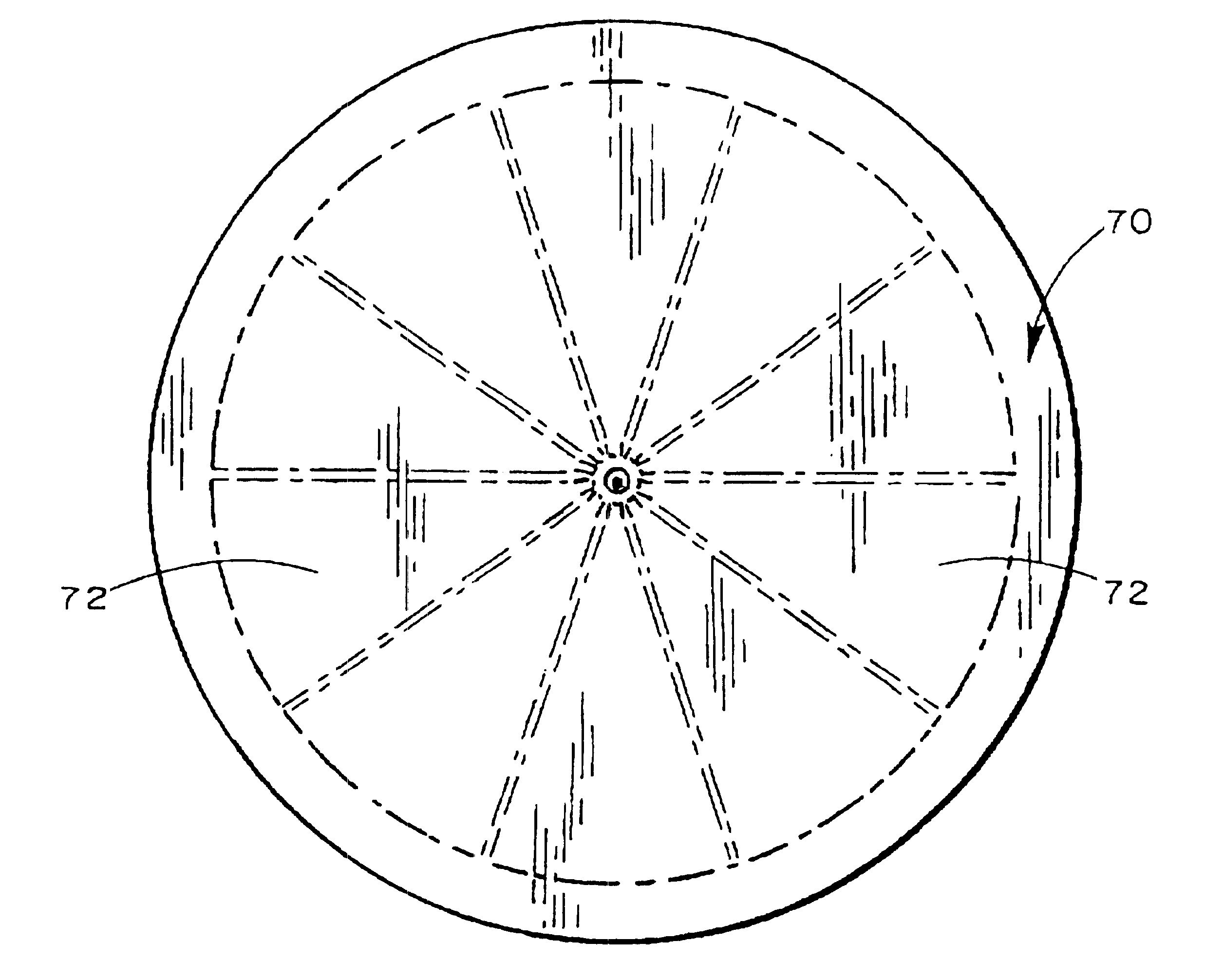
The electrode support assembly 20 comprises an array of flexible spline elements 22 assembled to form a three dimensional structure. The far ends of the spline elements 22 radiate from a distal hub. The near ends of the spline elements 22 are affixed to a base, which the distal end 16 of the catheter tube 12 carries.

Preferably, the spline elements 22 comprise thin, rectilinear strips of resilient metal or plastic material. Still, other cross sectional configurations can be used.

In the illustrated embodiments, the support assembly 20 retains the spline elements 22 in a three dimensional basket structure. Of course, the resulting structure can assume other shapes.

The probe 10 also includes an elect...


PUM


Abstract

An electrode support structure has a slotted hub and an integral body with a mid-section and opposed pair of spline elements that extend from the mid-section. The mid-section is captured within the slot, securing the integral body to the hub with the opposed spline elements radiating free of the slot for carrying one or more electrodes.

Description

FIELD OF THE INVENTIONThe invention relates to systems and methods for mapping and ablating the interior regions of the heart for treatment of cardiac conditions.BACKGROUND OF THE INVENTIONPhysicians make use of catheters today in medical procedures to gain access into interior regions of the body to ablate targeted tissue areas. It is important for the physician to be able to precisely locate the catheter and control its emission of energy within the body during tissue ablation procedures.The need for precise control over the catheter is especially critical during procedures that ablate endocardial tissue within the heart. These procedures, called electrophysiological therapy, are use to treat cardiac rhythm disturbances.During these procedures, a physician steers a catheter through a main vein or artery into the interior region of the heart that is to be treated. The physician then further manipulates a steering mechanism to place the electrode carried on the distal tip of the cat...

Claims


Application Information

Patent Timeline
IPC IPC(8): A61B5/0408A61B5/042A61B18/14A61B5/01
CPCA61B5/0422A61B5/6858A61B18/1492A61B2018/00267A61B2018/1407A61B2018/1435A61B2562/0209A61B2562/043A61B5/287
Inventor KORDIS, THOMAS F.
Owner EP TECH
Why Eureka
Try Eureka