Pipe insulation jacket

a technology of pipe insulation and jacket, which is applied in the direction of rigid pipes, pipes, heat exhanger conduits, etc., can solve the problem of not supporting the pipe to be insulated

Inactive Publication Date: 2002-10-08
INOFACE INT CO LTD
View PDF14 Cites 33 Cited by
  • Summary
  • Abstract
  • Description
  • Claims
  • Application Information

AI Technical Summary

Benefits of technology

Thus, it is an object of the invention to provide a pipe insulation jacket that ensures a safe and stable suspension or support of an insulated pipe, simultaneously having vibration-damping characteristics.
It is a further object of the present invention to provide a pipe insulation jacket that can be easily and inexpensively manufactured and that can be quickly attached to a pipe and handled without problems.
It is a still further object of the invention to provide a pipe insulation jacket that provides a good protection against humidity and / or steam penetrating into or escaping out of the insulation jacket.
Due to the fact that both hollow cylindrical jacket members are made of a dimensionally stable material, a safe and stable suspension or support is ensured. The insulation jacket is compressed only minimally upon attaching a pipe bracket, in contrast to pipe insulation jackets provided with soft, resilient portions. The elastic coating layer provided on the inner surfaces of the hollow cylindrical jacket members acts as a vibration damping element; moreover, certain tolerances regarding the outside diameter of the pipe to be insulated can be compensated, such that no undesired gap arises between the hollow cylindrical jacket members and the pipe. Since the elastic coating layer extends also over at least one of the two adjoining end faces at both sides of the insulation jacket, it is ensured that the two adjoining end faces fully contact each other thereby providing an excellent protection from moisture and steam possibly penetrating the interior of the insulation jacket or escaping therefrom.
The pipe insulation jacket can be quickly and easily attached to a pipe to be insulated. For that purpose, the two hollow cylindrical jacket members are spread apart at one side to form a gap having at least a width corresponding to the outer diameter of the pipe, such that the insulation jacket can be radially pushed over the pipe.

Problems solved by technology

A fundamental disadvantage of pipe insulation elements provided with flexible portions and suitable for serving as suspension or support sections may be seen in the fact that they are resilient under the influence of exterior forces, occurring for example whenever metallic pipe brackets are used, usually leading to a compression of these flexible portions with the result that the pipe to be insulated is not supported or suspended as stably as would be desired.

Method used


Image

  • Pipe insulation jacket
  • Pipe insulation jacket

Examples


Embodiment Construction

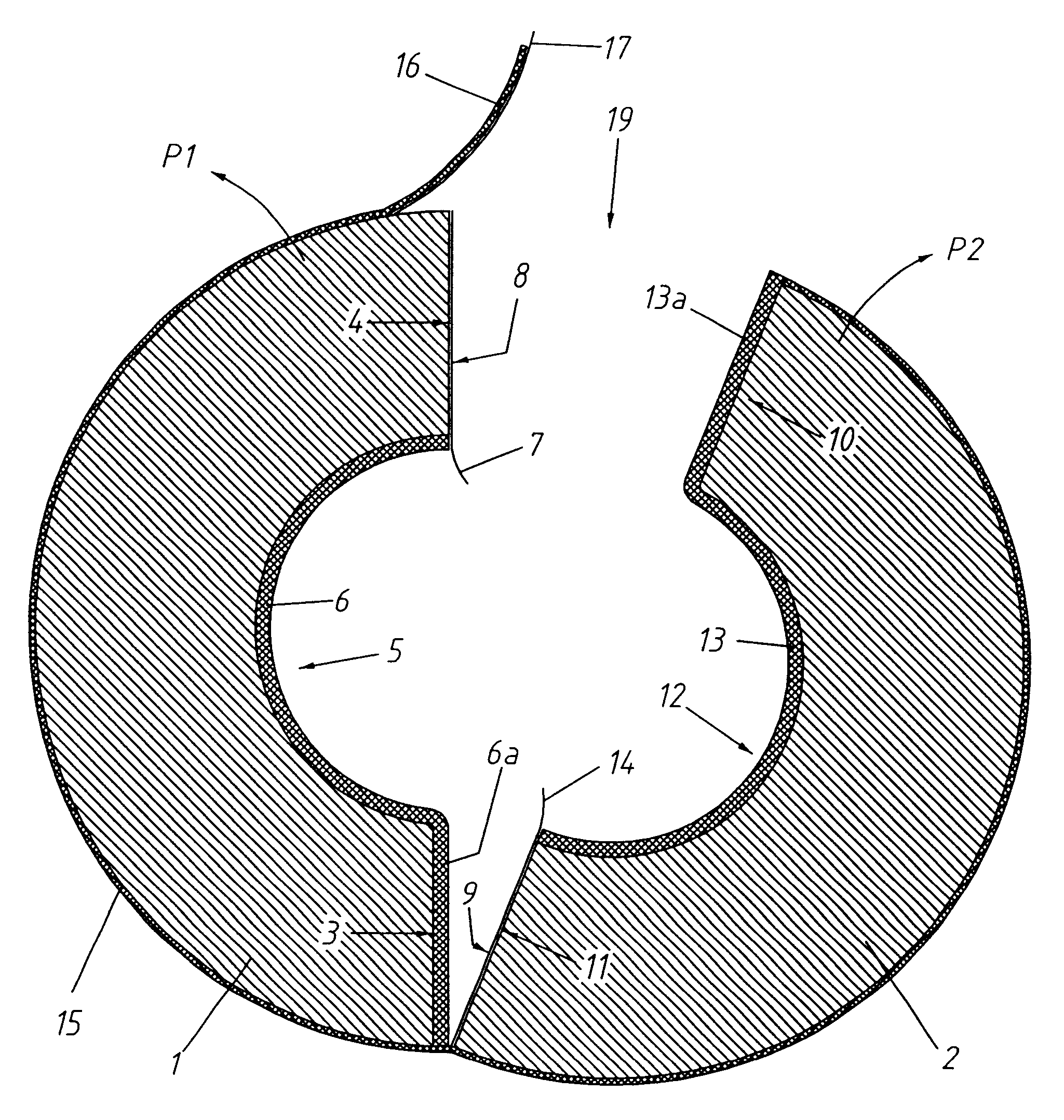
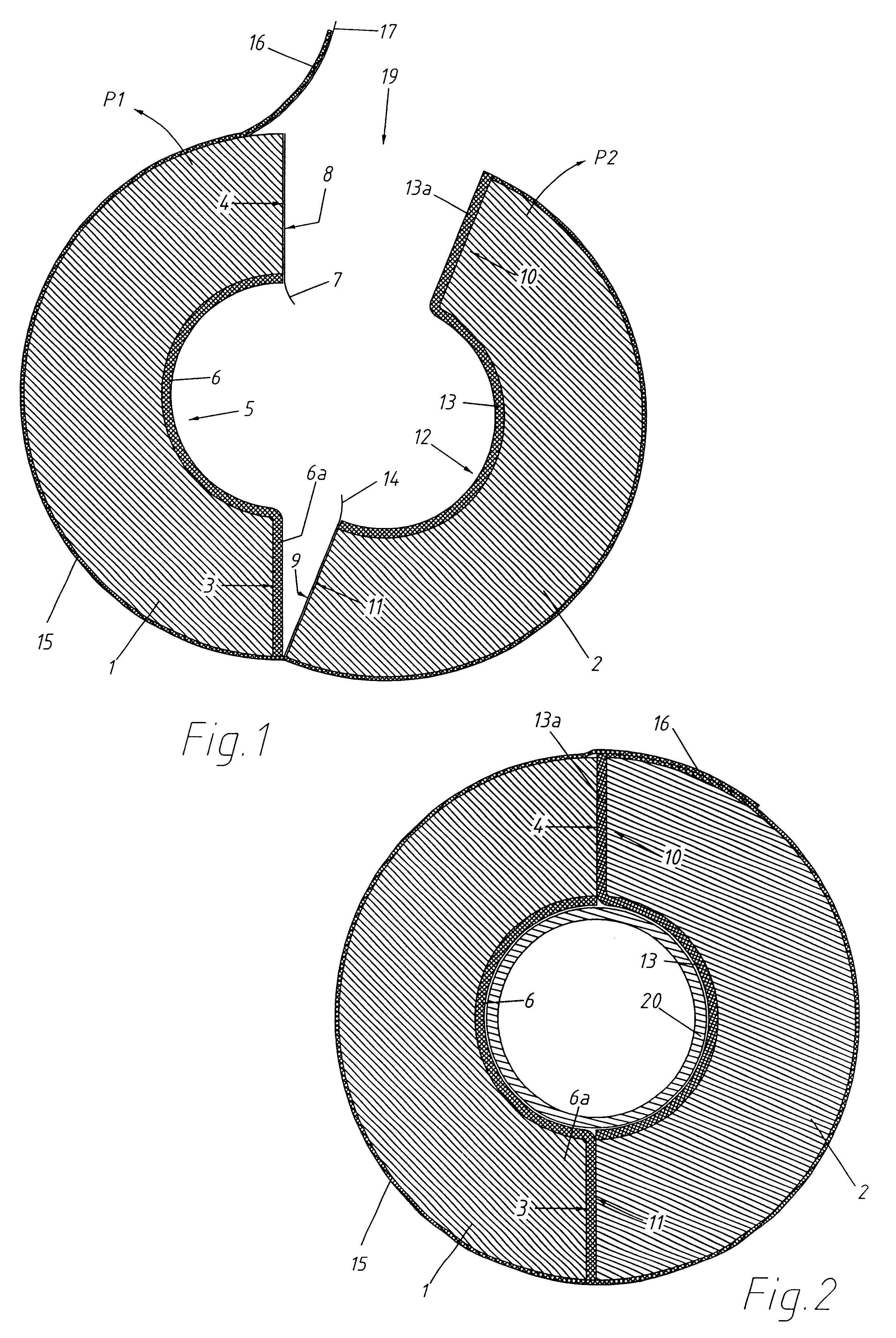
FIG. 1 shows a cross sectional view of the insulation jacket e.g. for thermally insulating a pipe, prior to applying it to the pipe. As can be seen in FIG. 1, the insulation jacket comprises a first jacket member 1 of hollow cylindrical configuration and a second jacket member 2 of hollow cylindrical configuration. The first and second jacket members 1, 2 are of dissymmetrically identical shape and are manufactured of a dimensionally stable, thermally insulating material, for example of a rigid foamed polyurethane material. Preferably, the outer surface of the jacket members 1, 2 is provided with a separate, smooth coating layer or an integral surface layer of smooth, not foamed polyurethane material.

The inner surface areas 5, 12 of the jacket members 1, 2 facing the outer surface of the pipe 20 (FIG. 2) are provided in each case with an elastic coating layer 6, 13 having vibration damping properties and being elastic in the direction of compression thereof. That coating layers 6, 1...


PUM


Abstract

A pipe insulation jacket comprises two jacket members that can be joined to form a hollow cylinder. Both jacket members are made of a dimensionally stable, thermally insulating material. Both jacket members are provided with an elastic coating layer extending over the inner surface and over one of the radially extending end faces of the jacket members. The outer surfaces of the two jacket members are covered by a common tape linking the jacket members at one side in such a way that they can be spread apart at the other to such an extent that the insulation jacket can be radially moved onto the pipe to be insulated. The tape extends over the jacket member at the side where the two jacket members are spread apart, and its inner side is provided with an adhesive layer to interconnect the two jacket members once the pipe is enclosed.

Description

The present invention refers to a pipe insulation jacket, comprising a first jacket member having the shape of a semi hollow cylinder and a second jacket member having the shape of a semi hollow cylinder. Both jacket members have substantially identical cross sectional shape and can be joined to form a hollow cylinder thereby enclosing a pipe to be insulated.Suspending or supporting thermally insulated pipes presents problems due to the fact that conventional insulators are not sufficiently strong for the brackets, by which the pipes are to be suspended or supported, to be attached to them. Therefore, pipe brackets are generally fixed directly to the pipe. This in turn requires additional insulation for the pipe brackets to prevent the formation of undesirable cold or heat bridges. It is obvious that providing additional insulation for pipe brackets is quite expensive.PRIOR ARTA pipe insulator for suspension or support of a pipeline with cold insulation is known from the document EP...

Claims


Application Information

Patent Timeline
Patent Type & Authority Patents(United States)
IPC IPC(8): F16L3/12F16L55/02F16L55/035F16L59/02F16L3/123
CPCF16L3/1233F16L55/035F16L59/023Y10S138/01
Inventor VITOORAPAKORN, PAWAT
Owner INOFACE INT CO LTD
Why Eureka
Try Eureka