Exhaust and control for watercraft engine

a technology for exhaust systems and watercraft, applied in the direction of propulsive elements, marine propulsion, vessel construction, etc., can solve the problems of exhaust leakage in the exhaust system, reducing the resiliency and and reducing the life expectancy of the coupling sleev

Inactive Publication Date: 2002-10-08
YAMAHA MOTOR CO LTD
View PDF24 Cites 39 Cited by
  • Summary
  • Abstract
  • Description
  • Claims
  • Application Information

AI Technical Summary

Problems solved by technology

The durable life of the coupling sleeve may be significantly shortened as a result of elevated temperatures and excessive vibrations within the exhaust system.
Additionally, environmental hazards such as sea salt and the like also may reduce the resiliency and the life expectancy of the coupling sleeve.
A combination of these elements may eventually cause the coupling sleeve to split, to crack or to otherwise fail, causing exhaust leaks in the exhaust system.
Moreover, in those instances where the coupling sleeve defines a portion of an exhaust system coolant jacket, a rupture of the coupling sleeve may cause a corresponding coolant jacket rupture.
The rupture may result in high temperature coolant flow and possible flooding within the engine compartment or another compartment.
Additionally, the cooling jacket that envelops a substantial portion of the exhaust system is susceptible to plugging.
Without adequate cooling, the exhaust system temperature may soar, possibly causing damage to temperature sensitive components within the engine compartment and the like.
Again, an improperly functioning cooling system can deteriorate the performance of such a catalytic device.

Method used


Image

  • Exhaust and control for watercraft engine
  • Exhaust and control for watercraft engine
  • Exhaust and control for watercraft engine

Examples


Embodiment Construction

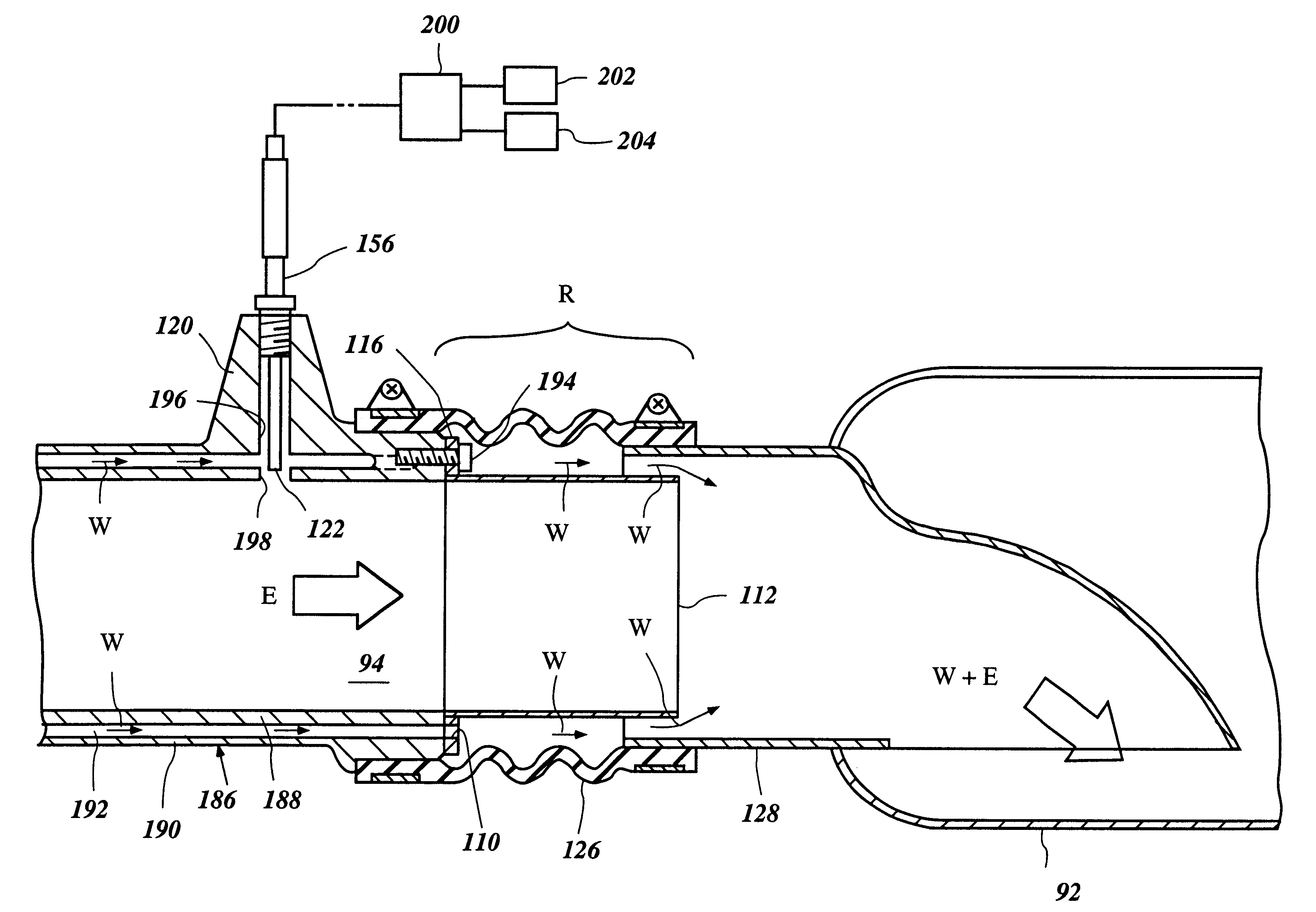
The present engine exhaust and cooling systems have particular utility with a personal watercraft, and thus, the following describes the engine exhaust and cooling systems in the context of a personal watercraft. This environment of use, however, is exemplary. The present engine exhaust and cooling system can be readily adapted by those of skill in the art for use with other types of watercraft as well, such as, for example, but without limitation, small jet boats and the like, as well as for use in other applications.

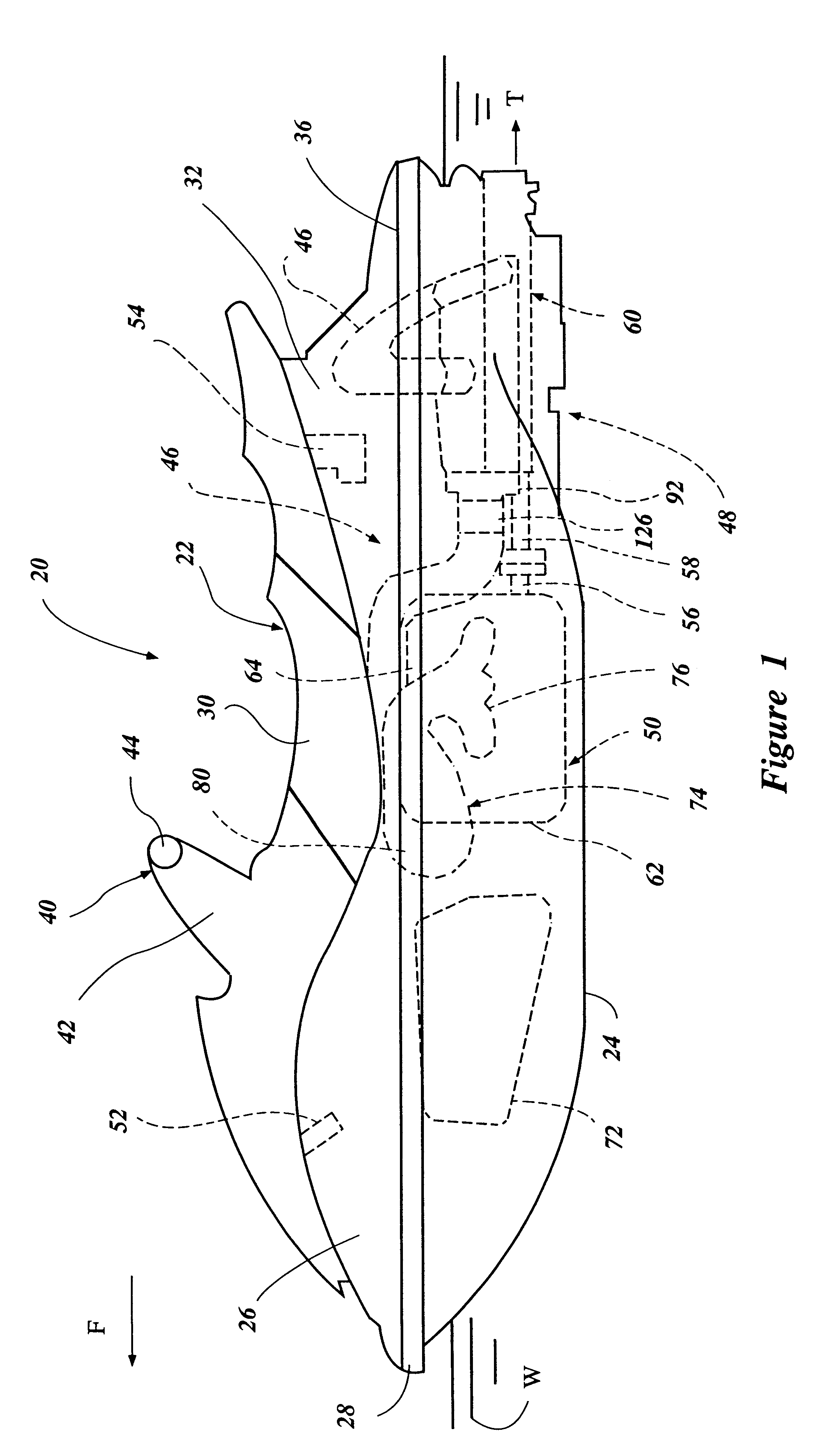
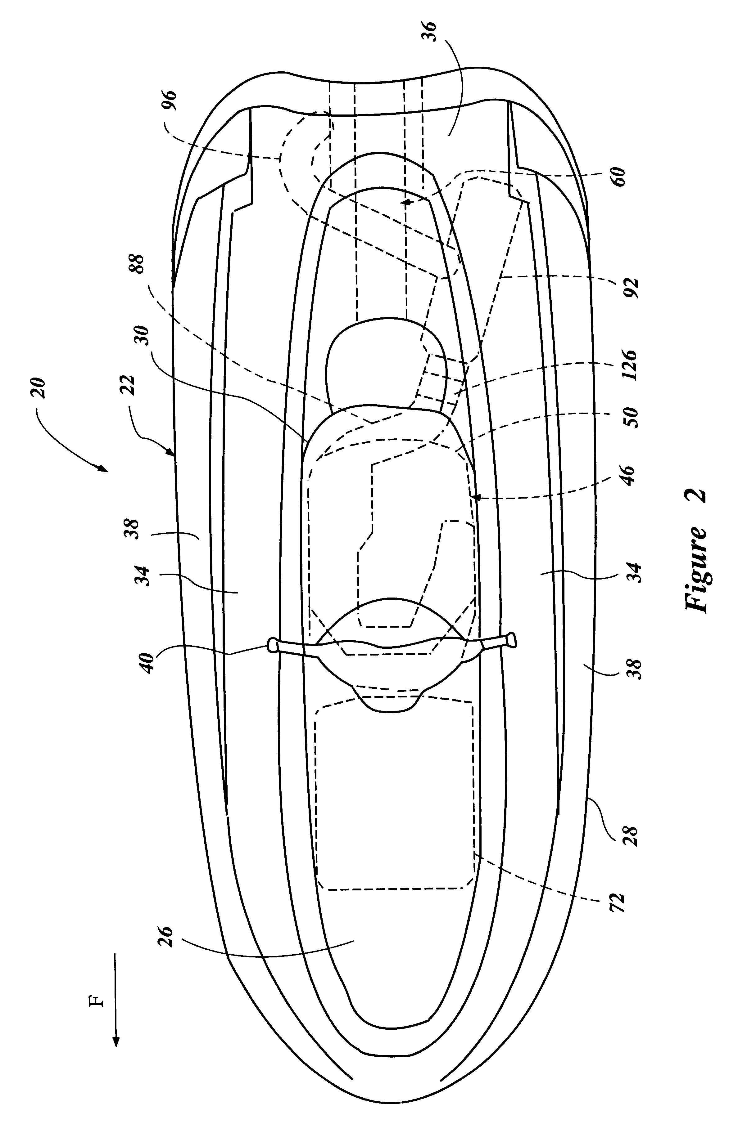
FIGS. 1 and 2 illustrate an exemplary watercraft 20. The illustrated watercraft 20 is desirably operated in a body of water designated by reference letter W in FIG. 1. In use, the watercraft 20 is propelled through the body of water W in a forward direction as designated by the arrow F in FIGS. 1 and 2.

The watercraft 20 is generally comprised of a watercraft body 22. The watercraft body 22 includes a hull 24 and a deck 26. A bond flange 28 is defined as the peripheral ...


PUM


Abstract

A watercraft has an exhaust system. The exhaust system has a first portion cooled by cooling jackets and a second portion cooled by merged flow. The first portion is coupled to the second portion with a flexible coupling having an undulating surface. An overheat detection system is positioned proximate the flexible coupling. The overheat detection system is arranged to detect a rapid increase in temperature resulting from a blocked cooling jacket. During periods of normal operation, a first temperature reading is detected. During periods of abnormal operation, a rapid increase in temperature indicates a sudden decrease in cooling water within the cooling jacket. Warning signals are emitted to the operator by an overheat prevention unit to advise the operator of the condition.

Description

1. Field of the InventionThe present invention relates to an exhaust system. More particularly, the present invention relates to an exhaust system of a personal watercraft.2. Description of Related ArtInternal combustion engines are used to power watercraft including watercraft commonly known as personal watercraft. Personal watercraft are generally distinguished from other types of watercraft by a characteristic open stem and a longitudinally extending straddle type seat. In fact, it is said that the operator sits upon a personal watercraft while the operator sits inside other watercraft.Personal watercraft include a hull which defines an engine compartment. An engine is mounted within the engine compartment and is arranged to drive a water propulsion device. Specifically, the output shaft of the engine is coupled to a water propulsion device of the watercraft, such as a water jet propulsion unit.The exhaust that is generated by combustion within the engine is routed through an exh...

Claims


Application Information

Patent Timeline
Patent Type & Authority Patents(United States)
IPC IPC(8): B63H21/32F01N3/28F01N3/04F01N7/00F01N7/18F01N7/12F02B61/00F02B61/04F02B75/02
CPCB63H21/32F01N3/043F01N3/28F01N13/004F01N13/008F01N13/12F01N13/1805F02B61/045F01N2590/022F02B2075/027Y02T10/20Y02T10/12
Inventor SUZUKI, AKITAKAKINOMOTO, NAOKIMASHIKO, TETSUYA
Owner YAMAHA MOTOR CO LTD
Why Eureka
Try Eureka