Container for a vial or ampoule

a container and ampoule technology, applied in the field of portable containers, can solve the problems of inability to protect the vial, the inability to heat the box, and the inability to transport, store and dispense vaccines in remote and underdeveloped areas

Inactive Publication Date: 2002-10-22
TRIPLE CCC CC
View PDF12 Cites 36 Cited by
  • Summary
  • Abstract
  • Description
  • Claims
  • Application Information

AI Technical Summary

Benefits of technology

It is accordingly an object of the present invention to provide a portable container for vials with which the aforesaid disadvantages may be overcome or minimised or to provide a useful alternative to the known vial containers.

Problems solved by technology

A disadvantages of these boxes is that the vials are not thermally insulated by the boxes during transportation and storage.
Transportation, storage and dispensing of these vaccines in remote and underdeveloped areas is relatively difficult, if not impossible with known vial containers.
A disadvantage of this is that the vials are unprotected from damage and because the vials are also usually made of glass, they will easily shatter in the event of the packet or box being dropped.

Method used


Image

  • Container for a vial or ampoule
  • Container for a vial or ampoule
  • Container for a vial or ampoule

Examples


first embodiment

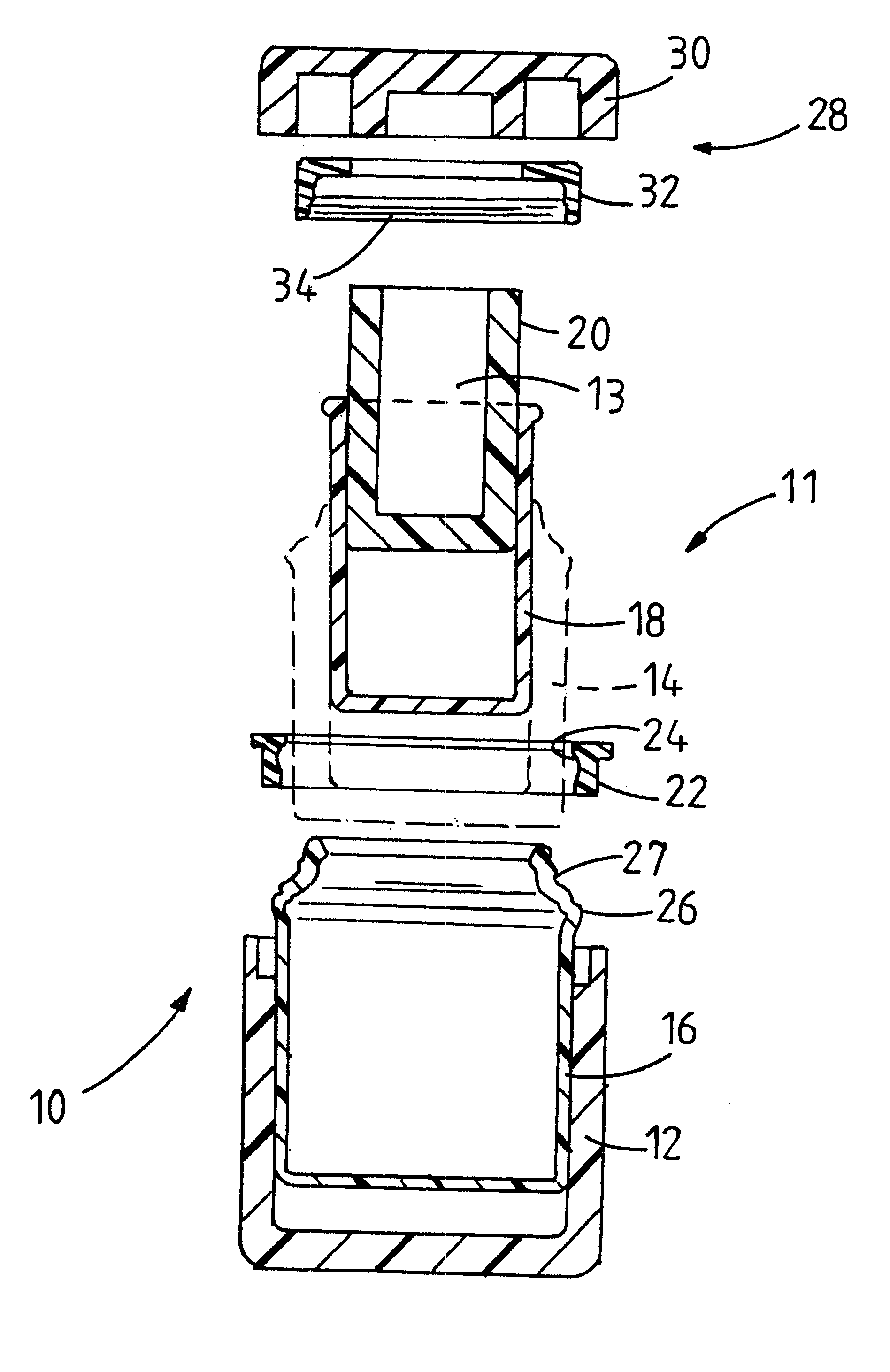
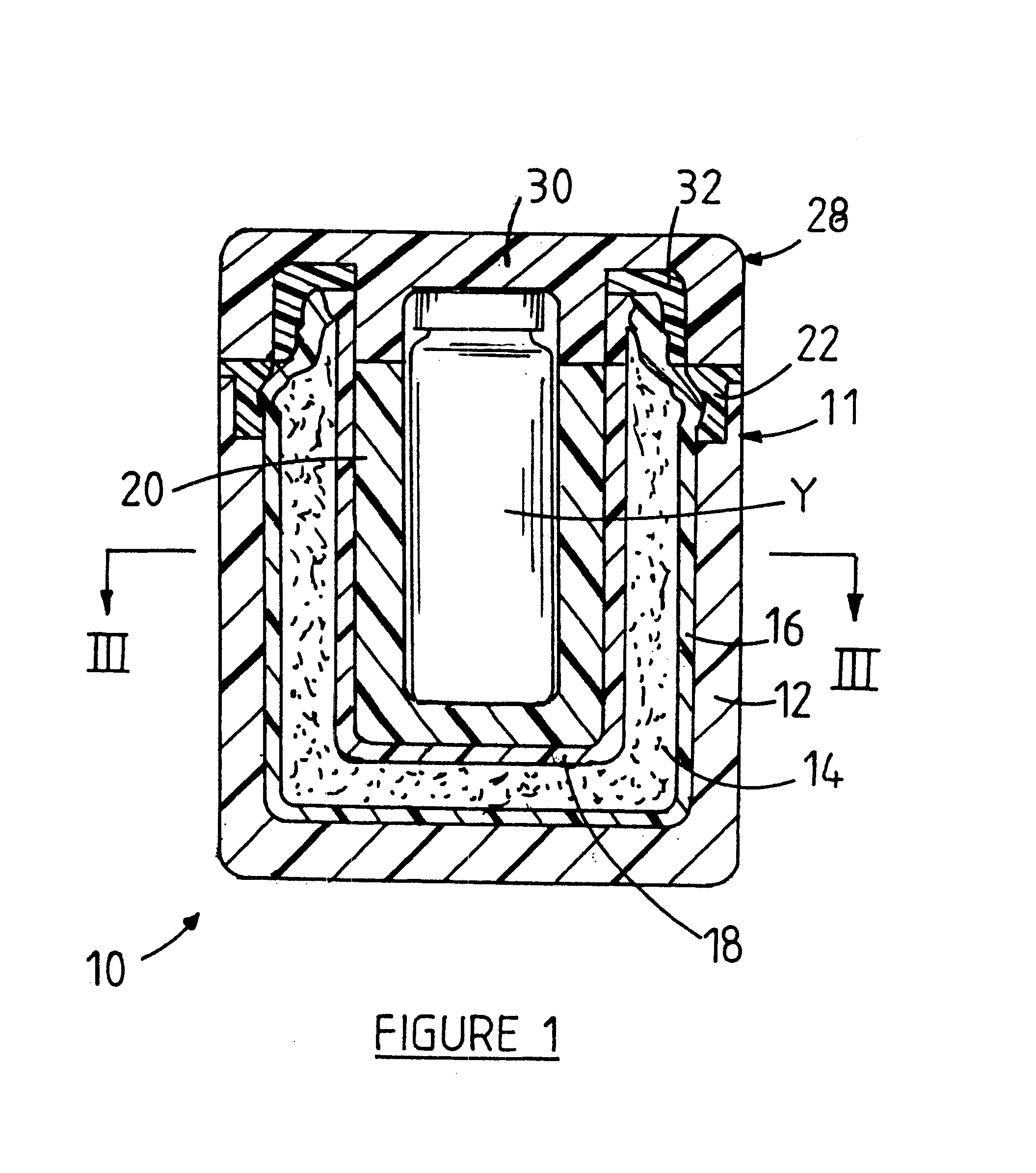
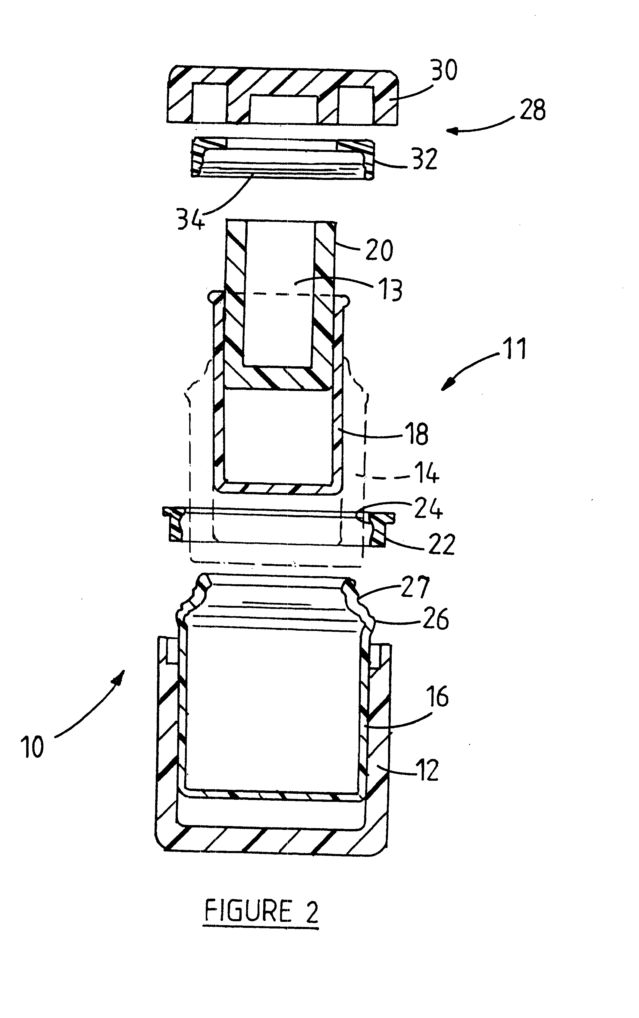
Referring to FIGS. 1 to 3, a portable container according to the invention, for a vial is generally designated by reference numeral 10.

The container 10 has a wall 11 defining a centrally located cavity 13 (FIGS. 2 and 3) for receiving a vial Y (FIG. 1). The wall 11 is constituted from four tubular blind ended concentrically disposed layers 12, 16, 18 and 20. The first and fourth layers 12 and 20 are of a thermally insulating material; preferably of polyurethane foam or expanded polystyrene foam.

The container 10 further includes a substance 14 for providing a passive cold source and surrounding the cavity 13. The substance 14 may be in solid, gel or liquid form, and is selected from the group including sodium acetate, polyethylene glycol, silicone based compounds, glycol alcohols, water, and polymers. Preferably the substance 14 comprises a gel of the type which is commonly used in cold packs with cooler boxes, the gel also being known as pharmaceutical gel. The substance 14 is dispo...

example

The efficiency of a container 10 according to the first embodiment was tested using a method including the steps of:

a) preparing an empty capped 10 ml vial by:

removing the cap of the vial;

inserting a suitable tube of a plastics material through the centre of the cap;

filling the vial with 10 ml water; and

replacing the cap;

b) storing the prepared vial in a refrigerator for at least 2 hours at a temperature of between 2 to 8 degrees Celsius;

c) opening the container and storing the container in a freezer at a temperature of approximately -20 degrees Celsius for at least 12 hours;

d) inserting a thermocouple through the tube into the vial and locating the thermocouple approximately in the centre of the vial;

e) placing the vial inside the container and closing the container by the lid and removing the container from the freezer; and

f) recording the temperature of the volume of water contained in the vial at regular intervals at an outside temperature of approximately 21 degrees Celsius.

The...

second embodiment

Referring to FIG. 4, a portable container according to the invention for a vial is generally designated by reference numeral 40. The container 40 is similar to the container 10, with the exception that the container 40 is relatively longer so that a plurality of vials Y can be received inside the container 40 in end to end relationship. A further exception is that the container 40 is provided with a protective coating 46 such as shrink wrap.


PUM


Abstract

A portable container (10) suitable for housing and protecting vials (Y) ampoules and other small vessels containing pharmaceutical or veterinary preparations such as vaccines, which are sensitive to changes in temperature or to relatively high temperature, is provided. The container (10) comprises a layered wall (11) defining a centrally located cavity (13) for receiving the vial (Y). The wall (11) includes an outer thermally insulating layer (12) surrounding a substance (14) for providing a passive cold source to the cavity (13) and two spaced inner layers (16 and 18) of a relatively hard plastics material providing an annular chamber wherein the substance (14) is received.

Description

INTRODUCTION AND BACKGROUND TO THE INVENTIONThis invention relates to a portable container which is specifically adapted for holding and protecting vials and ampoules and their contents. The articles to be protected will be termed vials in this specification, which term shall include within its scope ampoules, and other small vessels and their contents such as vaccines and the like. This invention further relates to a portable container for the passive cooling of vials. The container is particularly suitable for housing and protecting vials containing pharmaceutical or veterinary preparations such as vaccines which are sensitive to changes in temperature or to relatively high temperature.Vials are generally supplied in boxes, which may contain ten or more vials, to pharmacists, veterinary surgeons or other drug supply facilities. A disadvantages of these boxes is that the vials are not thermally insulated by the boxes during transportation and storage. Where the contents of the vial...

Claims


Application Information

Patent Timeline
Patent Type & Authority Patents(United States)
IPC IPC(8): A61J1/16A61J1/14B65D81/18F25D3/08F25D3/00
CPCA61J1/165B65D81/18F25D3/08F25D2303/0831F25D2331/8014F25D2331/804
Inventor COETZEE, JAN FREDERICK
Owner TRIPLE CCC CC
Why Eureka
Try Eureka