Moisture management system

a moisture management system and moisture management technology, applied in heat-proofing, building roofs, roofing, etc., can solve the problems of constant water damage, infiltration of rainwater, and inability to apply foaming siding to the exterior of buildings, and achieve the effect of improving the adhesion of sealants and adhesives

Inactive Publication Date: 2002-10-29
PLASTIC COMPONENTS
View PDF4 Cites 194 Cited by
  • Summary
  • Abstract
  • Description
  • Claims
  • Application Information

AI Technical Summary

Benefits of technology

According to the present invention, there is provided an improved moisture management system for installation over doors and windows in buildings that included exterior, stucco-covered, curtain walls comprising an integrally formed, three sided, elongated track including a base, an upright front wall that includes at its base weep holes for the removal of entrained moisture as well as a longitudinal forward extending finish stop, and an upright rear wall at opposing elongated edges of

Problems solved by technology

The infiltration of water into buildings and other structures particularly at the top of windows, doors etc as well at the base of so-called stucco-covered, curtain type, foamed siding applied to the exterior of buildings is a constant problem in both new and retrofit construction.
Such wall structures, in some instances can be exposed to rain driven by winds; as high as 90 miles per hour in certain areas, and consequently are vulnerable to infiltration of wind driven rain as well as insufficient drainage of accumulated water from the area between the exterior curtain wall and the interior supporting shell of the wall construction.
Particularly vulnerable to infiltration of rainwater in this fashion are the area

Method used


Image

  • Moisture management system
  • Moisture management system
  • Moisture management system

Examples


Embodiment Construction

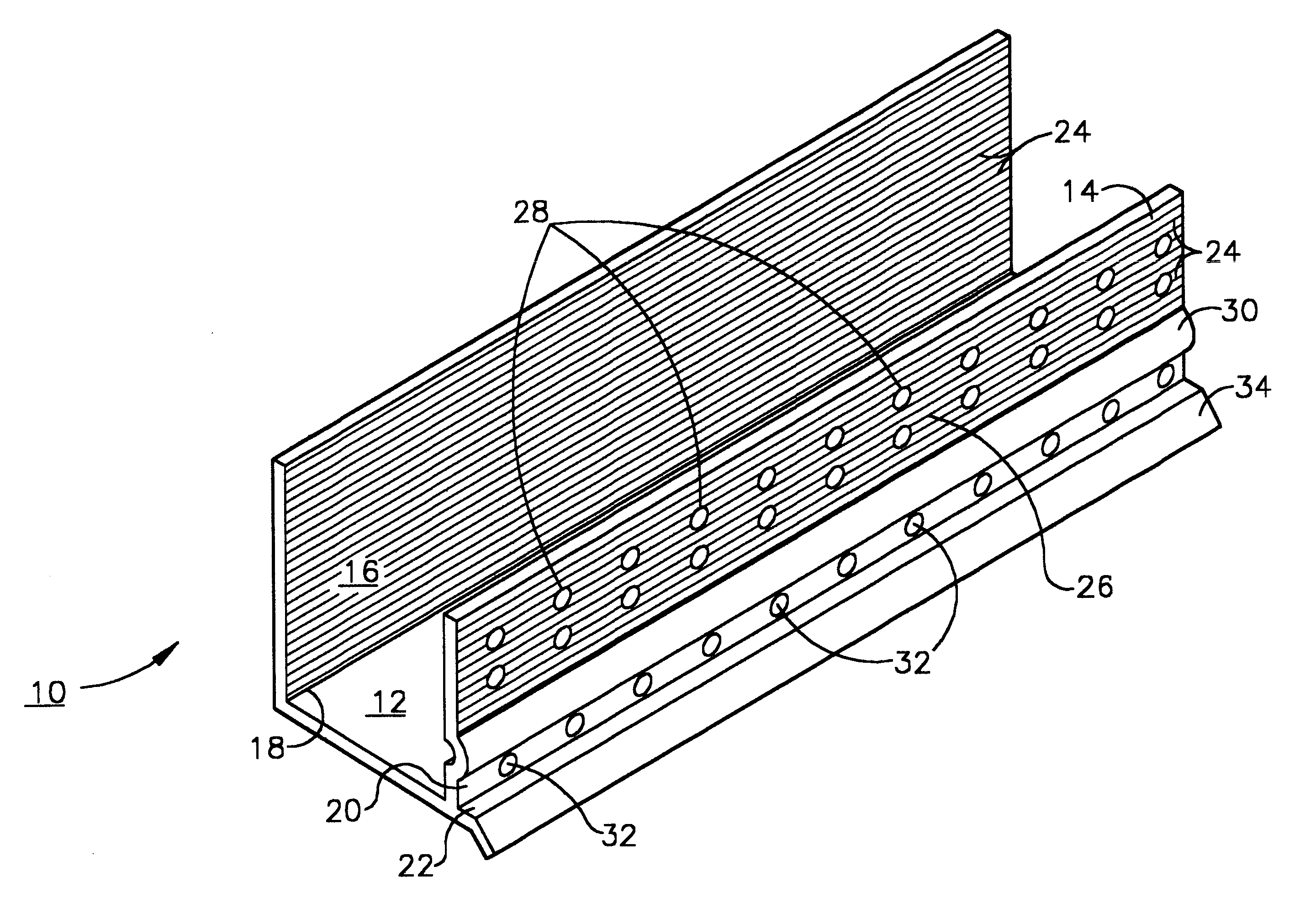
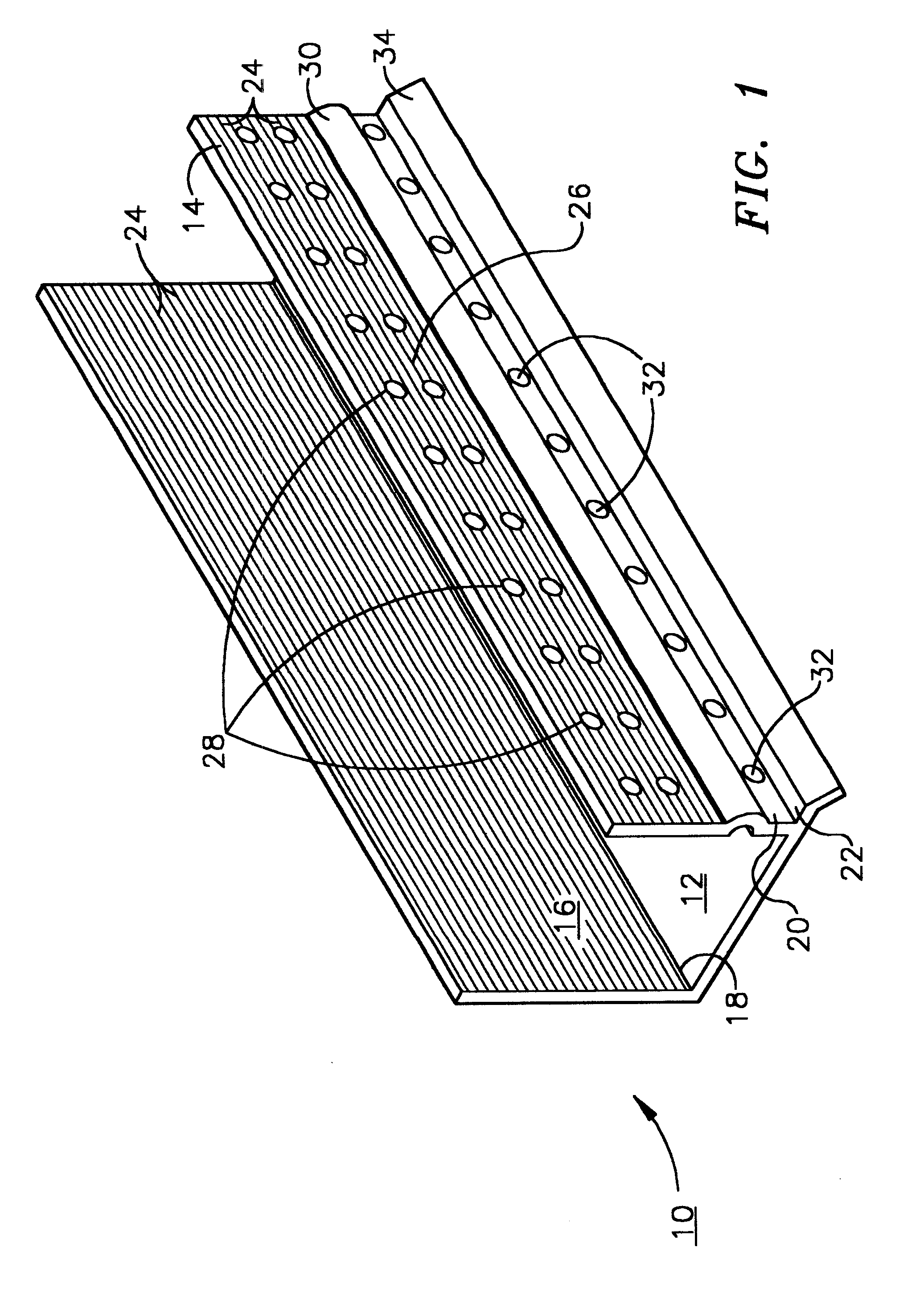
The invention described herein is similar to that described in U.S. patent application Ser. No. 08 / 807,655 filed Feb. 27, 1997 which application is hereby referred to and incorporated by reference herein.

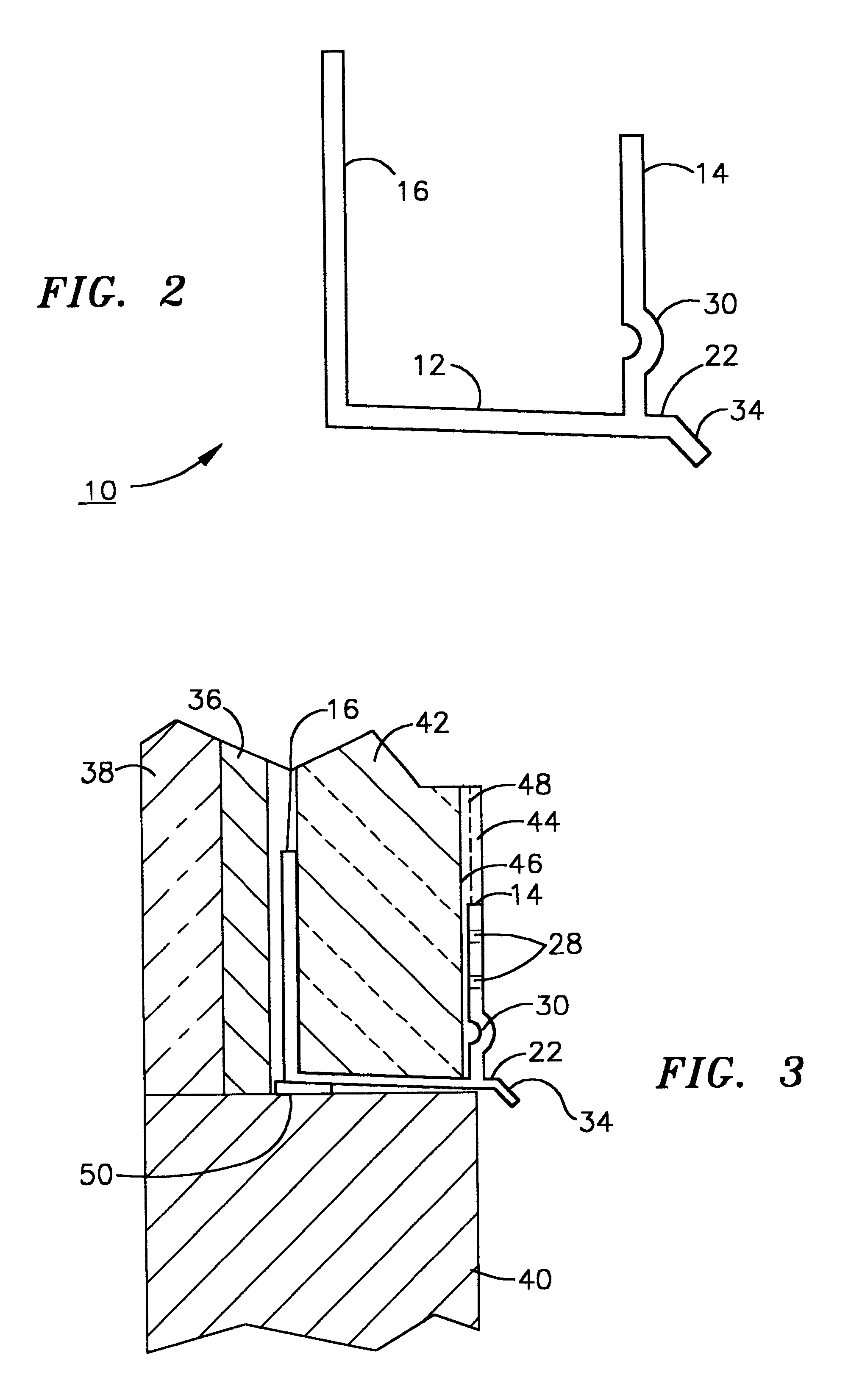
As shown in FIG. 1, the moisture management system 10 of the present invention comprises an elongated, generally U-shaped, channel having a base 12, an upstanding front wall 14 and an upstanding rear wall 16 extending vertically, longitudinally and in generally parallel relationship from elongated edges 18 and 20 of base 12, and drip plate 22 integrally formed with base 12 and extending angularly therefrom. The front of both upstanding front wall 14 and rear wall 16 preferably include parallel striations 24 and 26 across their entire length. Front upstanding wall 14 further includes holes 28 therein. Upstanding front wall 14 additionally includes longitudinal finish stop 30 above weep holes 32, i.e. such that weep holes 32 lie between front elongated edge 20 and finish stop 30. The ...


PUM

PropertyMeasurementUnit
Thicknessaaaaaaaaaa

Abstract

An improved moisture management system for installation over doors and windows in buildings that included exterior, stucco-covered, curtain walls comprising an integrally formed, three sided, elongated track including a base, an upright front wall that includes at its base weep holes for the removal of entrained moisture as well as a longitudinal forward extending finish stop above the weep holes, and an upright rear wall at opposing elongated edges of the base, and, extending angularly downward from the outside of the base, and integrally formed therewith, a drip plate that permits ready drainage of water exiting the moisture management system through the weep holes in the upright front wall. Preferably, elongated striations in the front faces of both the front and rear upright walls as well as holes in the upright front wall above the finish stop provide improved adherence of sealants and adhesives used in the installation process.

Description

The present invention relates to moisture management systems for use over windows, doors and other building openings on buildings where so-called stucco covered, curtain type foamed siding is applied to the exterior of a building. Such moisture management systems inhibit the infiltration of water into the building at the top of such openings by providing a path for the potentially infiltrating water to take away from the surface of the building. The moisture management system described herein is also useful at the base of such exteriorly applied foamed siding to prevent water infiltration.The infiltration of water into buildings and other structures particularly at the top of windows, doors etc as well at the base of so-called stucco-covered, curtain type, foamed siding applied to the exterior of buildings is a constant problem in both new and retrofit construction.The term curtain wall refers to a type of building construction in which an exterior non-load-bearing wall is supported...

Claims


Application Information

Patent Timeline
IPC IPC(8): E04B1/76E04F19/02E04F13/02E04F13/06
CPCE04B1/765E04F13/06E04F19/02E04F13/068E04F2013/065E04F2013/063
Inventor LARSON, JOHN A.
Owner PLASTIC COMPONENTS
Why Eureka
Try Eureka