
Polycyclonic vacuum collectors for virtually non-stop environmental remediation

a vacuum collector and polycyclonic technology, applied in the field of vacuum collectors, can solve the problems of unsuitable vacuum loaders for challenging operations, unsuitable unsuitable vacuum loaders for rapid, efficient cleaning of heavily contaminated areas, etc., to maximize collector efficiency and capacity, high contaminant processing capability, and high contaminant storage capacity

Inactive Publication Date: 2002-10-29
HOUSTON INDAL CORP
View PDF7 Cites 67 Cited by
  • Summary
  • Abstract
  • Description
  • Claims
  • Application Information

AI Technical Summary

Benefits of technology

It is easily seen that the purity of air going through the filters above the last drum increases with the number of cyclonic drums in the collector, especially where the collector employs cyclonic chambers of different cleaning selectivities. Thus, the invented collector enables control of purity of air going through filters, which air purity determines filter lifetime. And since filter clogging is a primary cause for interrupting vacuum cleaning, and costly filter replacement a main contributor to cleaning cost, the invented collector enables environmental remediation that is both virtually nonstop and relatively inexpensive.
Thus, a novel polycyclonic collector has been invented, which saves the environment, protects health, and insures enforcement of the federal environmental laws.

Problems solved by technology

Lack of powerful cyclonic cleaning, among other things, makes this vacuum loader unsuitable for challenging operations.
Although more potent than analogous non-cyclonic appliances, this appliance cannot efficiently clean heavily contaminated areas, because, among other deficiencies, it has only one cyclone.
Although this vacuum cleaner minimizes size by artfully combining cyclonic cleaning, contaminant storage, and primary as well as secondary filtration within a single module, its peculiar use of the primary filter surface as contaminant storage site renders it unsuitable for rapid, efficient cleaning of heavily contaminated areas.
With only one cyclone, this dust collector lacks the power for challenging cleaning operations.
Although this DeMarco loader features two communicating cyclone chambers, it comes with many components and great complexity, which combine to decrease usefulness in several ways.
First, cleaning the secondary (HEPA) filters of the loader, an important maintenance task, can be messy and dangerous, because the secondary filters are separate from the primary filters, in a distant module lacking a contaminant storage chamber.
And when they are taken out and cleaned, contaminants adhering on the filters fill the air and proceed to land nearby, which is primarily the face of the person cleaning the filters.
Contaminants, especially toxic contaminants, on the face or in the lungs of the operator of the loader, every time the secondary filters need cleaning, is an important limitation of the DeMarco loader.
Second, the loader is less durable and more expensive to maintain than it could have been, because it has many moving parts which do not participate in air cleaning and contaminant storing, such as valves, pistons, a complicated device operating the bagger, etc.
Third, the loader features low design and construction economy with respect to air cleaning and contaminant storing, because most components of the loader neither clean air nor store contaminants--instead, they perform functions such as transferring contaminants from a storage site to a bagger, operating the bagger, etc.
This low design and construction economy brings disadvantages, including relatively (1) low efficiency, (2) low capacity, (3) high structural and operational complexity, (4) high purchase price, and (5) expensive maintenance.
Indeed these disadvantages can be seen in action in the requirement for an unusually powerful vacuum-producing motor--a 80 hp motor--for production of a relatively low vacuum--217 inches on the water scale--inside this loader.
Design and construction limitations seriously limit the cleaning power of this loader.
Due to limitations relating to cleaning power, maintenance, durability, capacity, efficiency, cost, and operability, the DeMarco loader is no solution to the challenge of large-scale environmental remediation.

Method used


Image

  • Polycyclonic vacuum collectors for virtually non-stop environmental remediation
  • Polycyclonic vacuum collectors for virtually non-stop environmental remediation
  • Polycyclonic vacuum collectors for virtually non-stop environmental remediation

Examples


embodiment 10

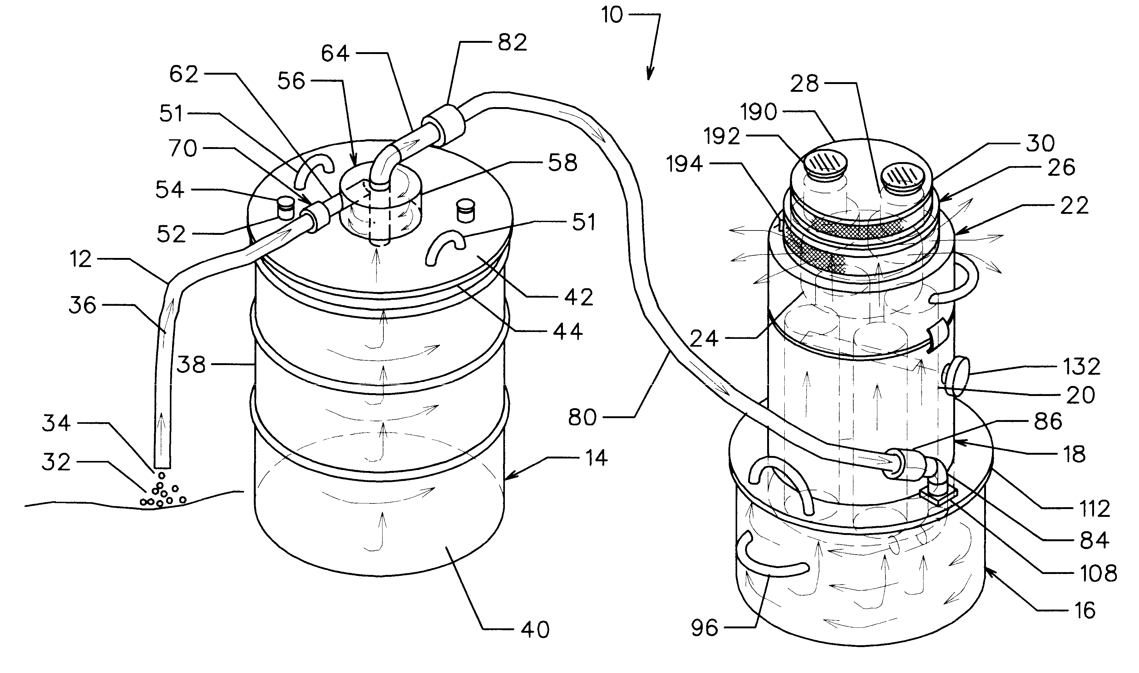
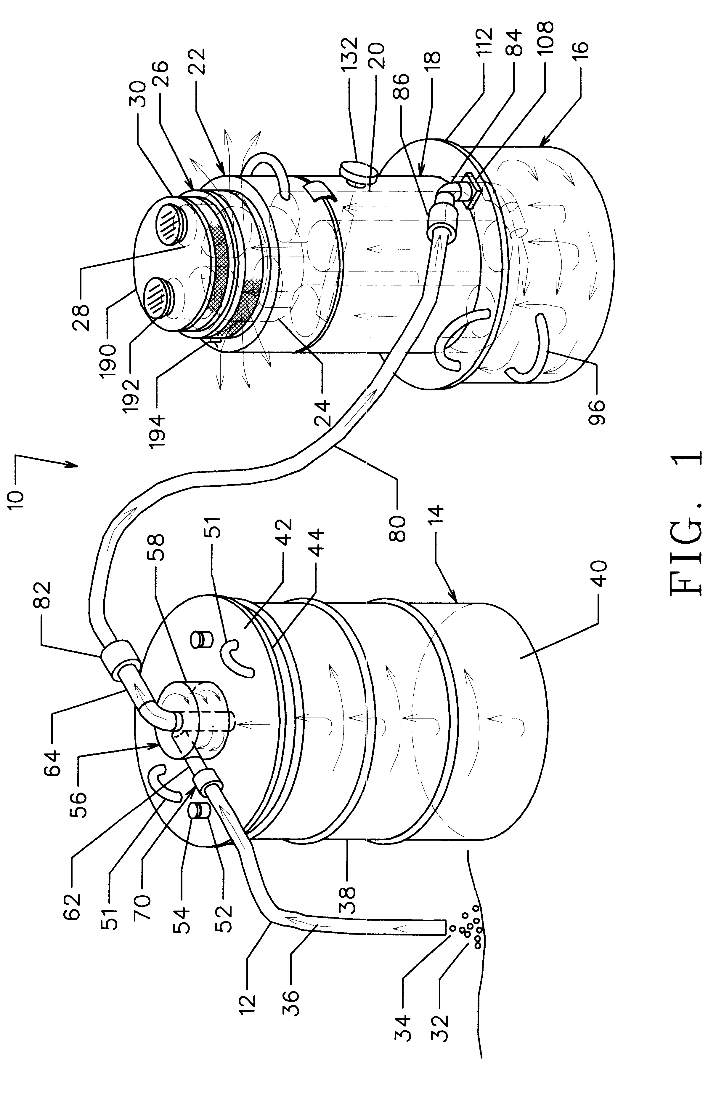
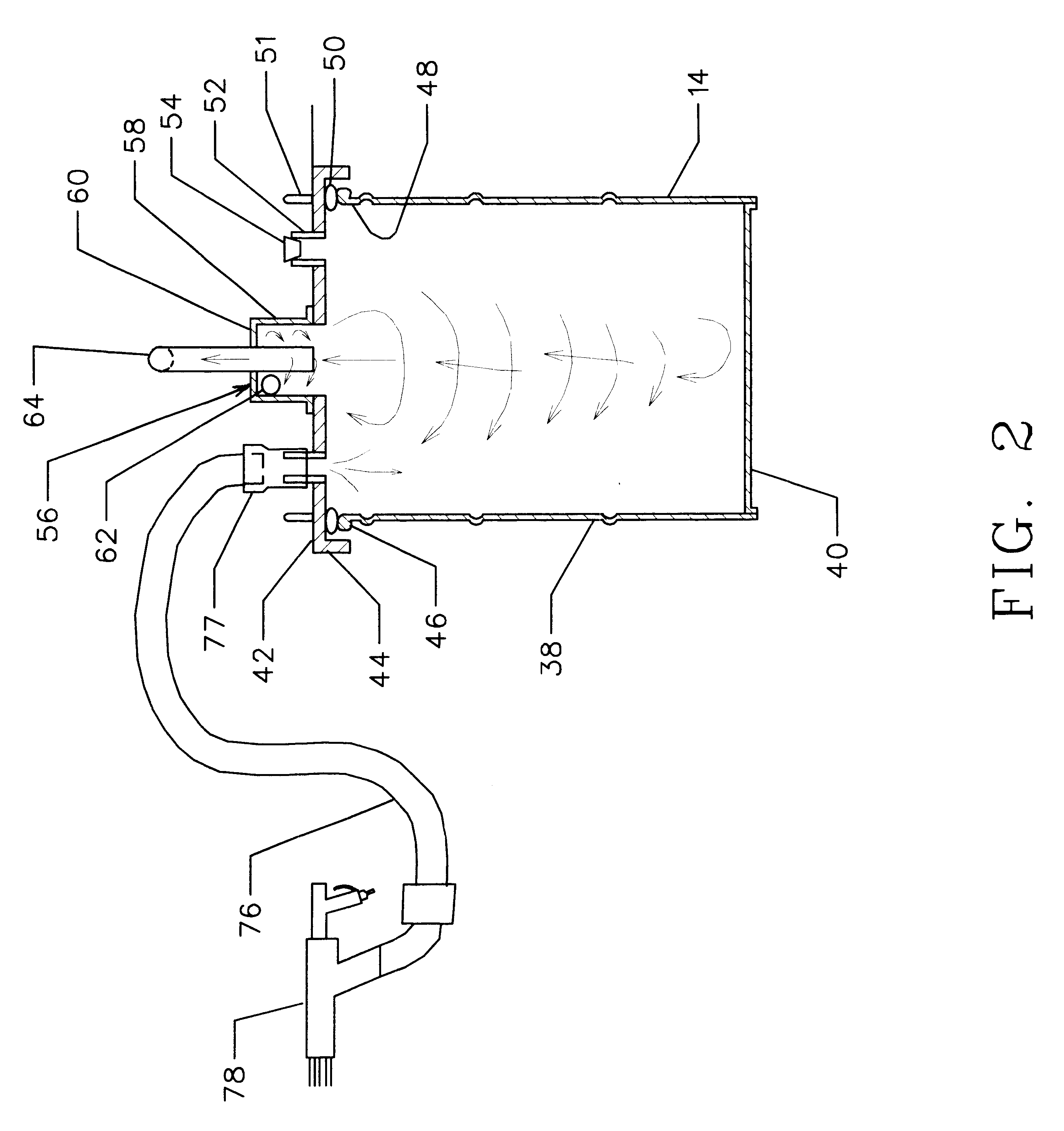
Preferred embodiment 10 of the invented polycyclonic vacuum collector, shown in FIG. 1, is bicyclonic, comprising a vacuum hose 12, a first drum 14, a second drum 16, a primary filter housing 18 containing primary filters 20, a HEPA filter housing 22 containing a HEPA filter 24, a motor housing 26 containing two motors 28, and a motor cover 30. Vacuum hose 12 communicates with first cyclonic drum 14, which communicates with second cyclonic drum 16, which communicates primary filter housing 18, which communicates with HEPA filter housing 22, which communicates with motors 28. The purpose of motors 28 is to pull a vacuum. When the motors pull a vacuum, a negative pressure develops inside collector 10, i.e., the pressure inside the collector is lower than the pressure outside, which pressure difference enables vacuum hose 12 to suck air from the atmosphere mixed with contaminants 32 on a surface under open end 34 of vacuum hose 12. This suction produces a flow of contaminant-laden air ...

embodiment 196

Additional embodiment 196 of the present invention, shown in FIG. 10, is the preferred embodiment of FIG. 1 with this difference: interposed between and communicating with first and second cyclonic drums 14 and 16 is a cyclonic drum 198 taken from the prior art. Cyclonic drum 198 has a cyclone generator 200. The cyclone generator 200 shown in FIG. 10 has a helical roof; it is a prior art cyclone generator and can, e.g., be replaced by any of the prior art cyclone generators shown in FIG. 11. Helical-roof cyclone generator 200, as well as those of FIG. 11, are discussed in Design of Industrial Ventilation Systems, J. L. Alden and J. M. Kane, Industrial Press Inc., New York, N.Y. 1982. Cyclone generator 200 of FIG. 10 has a side wall with a cylindrical upper section 202 and a conical lower section 204, a top wall 206, an inlet port 208, a bent outlet port 210, and a helical roof 212 inside the space defined by cylindrical upper section 202. Conical lower section 204 has an opening 211...

embodiment 224

Alternative embodiment 224 shown in FIG. 12 modifies the preferred embodiment of FIG. 1 by interposing between and connecting with first cyclonic drum 14 and second cyclonic drum 16 n-2 communicating cyclonic drums, where n is an integer greater than 3. In FIG. 12, C.sub.1 represents the first cyclonic drum 14 of FIG. 1 connected to a vacuum (suction) hose 226; C.sub.n represents the second cyclonic drum 16 of FIG. 1 carrying the stack of (a) primary filter housing 18 containing primary filter bags 20, (b) HEPA filter housing 22 containing HEPA filter 24, (c) motor housing 26 containing motors 28, and (d) motor cover 30. Cyclonic drums C.sub.2 and C.sub.m are known in the art, e.g., they can be assembled using drums and the cyclone generators of FIG. 11. Dots 228 between symbols C.sub.2 and C.sub.m, and between C.sub.m and C.sub.n represent additional prior art cyclonic drums, which are part of the chain of communicating cyclonic drums of the polyccyclonic assembly 224. Lines 230 re...


PUM

PropertyMeasurementUnit
Angleaaaaaaaaaa
Angleaaaaaaaaaa
Poweraaaaaaaaaa

Abstract

A vacuum collector is provided comprising a suction hose, a first drum with a cover having a cylindrical head capable of generating powerful, small-diameter cyclones, a second drum capable of generating large-diameter cyclones, and a stack of three modules containing vacuum-producing motors atop a HEPA filter atop primary filters. The suction hose is connected to the inlet of the small-diameter cyclone-generating head on the cover of the first drum. The stack of modules containing motors, HEPA filter, and primary filters is mounted on the second drum. The two cyclonic drums communicate through a flexible vacuum hose. When the vacuum-producing motors pull air from the interior of the vacuum collector, the suction hose sucks atmospheric air mixed with contaminants from a surface into the head, which spins the contaminant-laden air-stream into a powerful, small-diameter cyclone. As a result of cyclonic action, the contaminant laden air-stream spirals to the bottom of the first drum, deposits most of its contaminants, reverses course, exits the drum, and enters the second drum, where it spins into a large-diameter cyclone, deposits more contaminants, passes through the primary and HEPA filters, and exhausts via the vacuum-producing motors. Collectors comprising more than two communicating cyclonic drums for tailored environmental remediation are also described.

Description

1. CROSS-REFERENCE TO RELATED APPLICATIONSNot applicable2. FIELD OF THE INVENTIONThis invention relates to vacuum collectors, specifically to cyclonic vacuum collectors employing HEPA (High Efficiency Particulate Air) filters to achieve large-scale environmental remediation.3. BACKGROUND3.1. Environmental Remediation: A Critical Problem Accompanying SandblastingSandblasting is an important preliminary to the painting of large metallic structures, e.g., bridges. Sandblasting removes old paint and cleans the bridge to be painted. Sandblasting produces large quantities of reactive, toxic dust. Significant amounts of neurotoxic lead, carcinogenic chromium, and other highly toxic materials make this dust very dangerous. Collecting paint dust from sandblasted bridges in a safe manner is necessary and presently extremely difficult. Federal regulations require that vacuum collectors picking up paint dust have HEPA filters to ensure their exhaust is better than 99.97% free of dust particles ...

Claims


Application Information

Patent Timeline
IPC IPC(8): B01D46/04B01D45/12B01D50/00B01D46/00B01D46/24
CPCB01D45/12B01D46/0075B01D46/04B01D46/2411B01D50/002B01D46/76B01D50/20
Inventor SEMANDERES, STAVROSLUNARDINI, JOHN M.
Owner HOUSTON INDAL CORP
Learn More