Modular converter

a converter and module technology, applied in the field of new converters, can solve the problems of relatively high manufacturing cost and box separation from the motor, and achieve the effect of easily replacing faulty electronic cards

Inactive Publication Date: 2002-10-29
MOTEURS LEROY SOMER
View PDF13 Cites 26 Cited by
  • Summary
  • Abstract
  • Description
  • Claims
  • Application Information

AI Technical Summary

Benefits of technology

The invention seeks to provide a novel converter which makes it possible in particular to replace faulty electronic cards easily.
In addition, the fins remain relatively short and they harden quite quickly, thereby making high rates of throughput possible with injection molding.

Problems solved by technology

The drawback of such known converters is that in the event of an electronic failure, it is necessary to replace the entire box, which means that the box must be separated from the motor.
Furthermore, each box is specific to a given motor which gives rise to relatively high manufacturing costs when a motor is made in a short manufacturing run only.

Method used


Image

  • Modular converter
  • Modular converter
  • Modular converter

Examples


Embodiment Construction

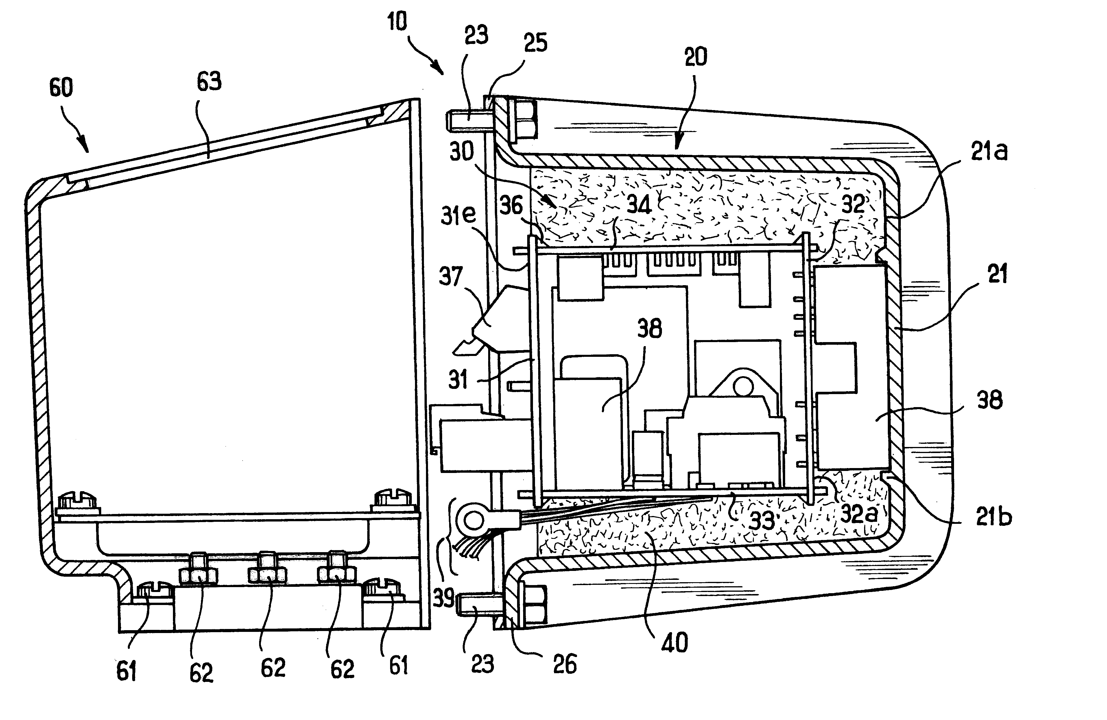
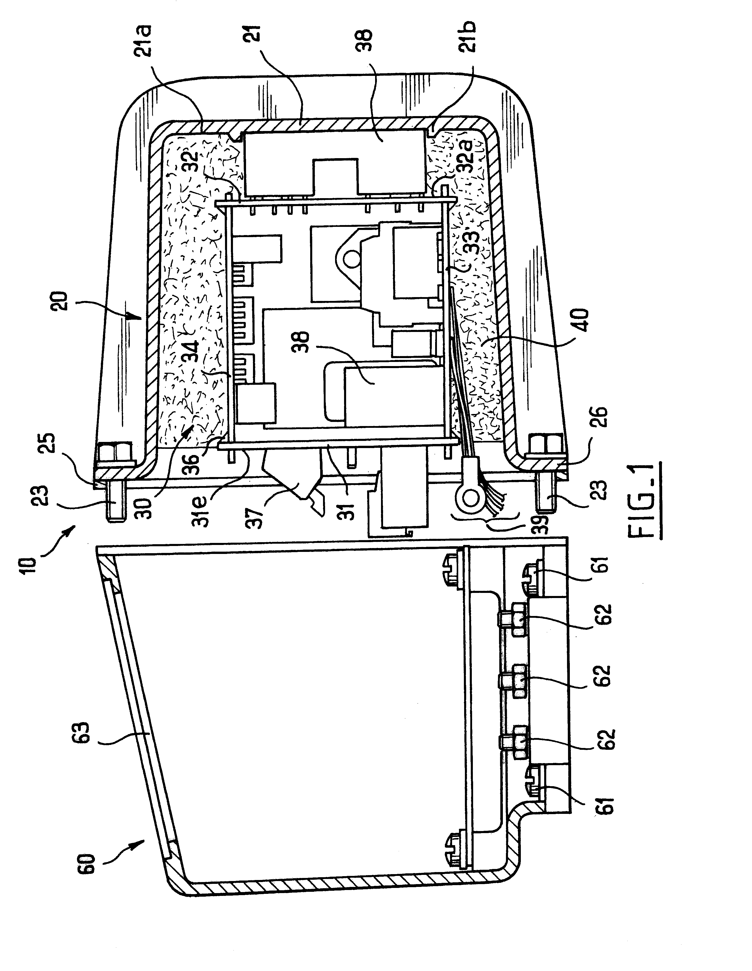
FIG. 1 shows a converter of the invention, containing an electronic module 10 of power lying in the range 0.25 kilowatts (kW) to 15 kW, for example, and comprising a radiator-forming box 20 that is open to the front and made by injection molding aluminum, the box containing a set of electronic cards 30 constituted in this case by four electronic cards, namely a front card 31, a rear card 32, and two intermediate cards 33 and 34.

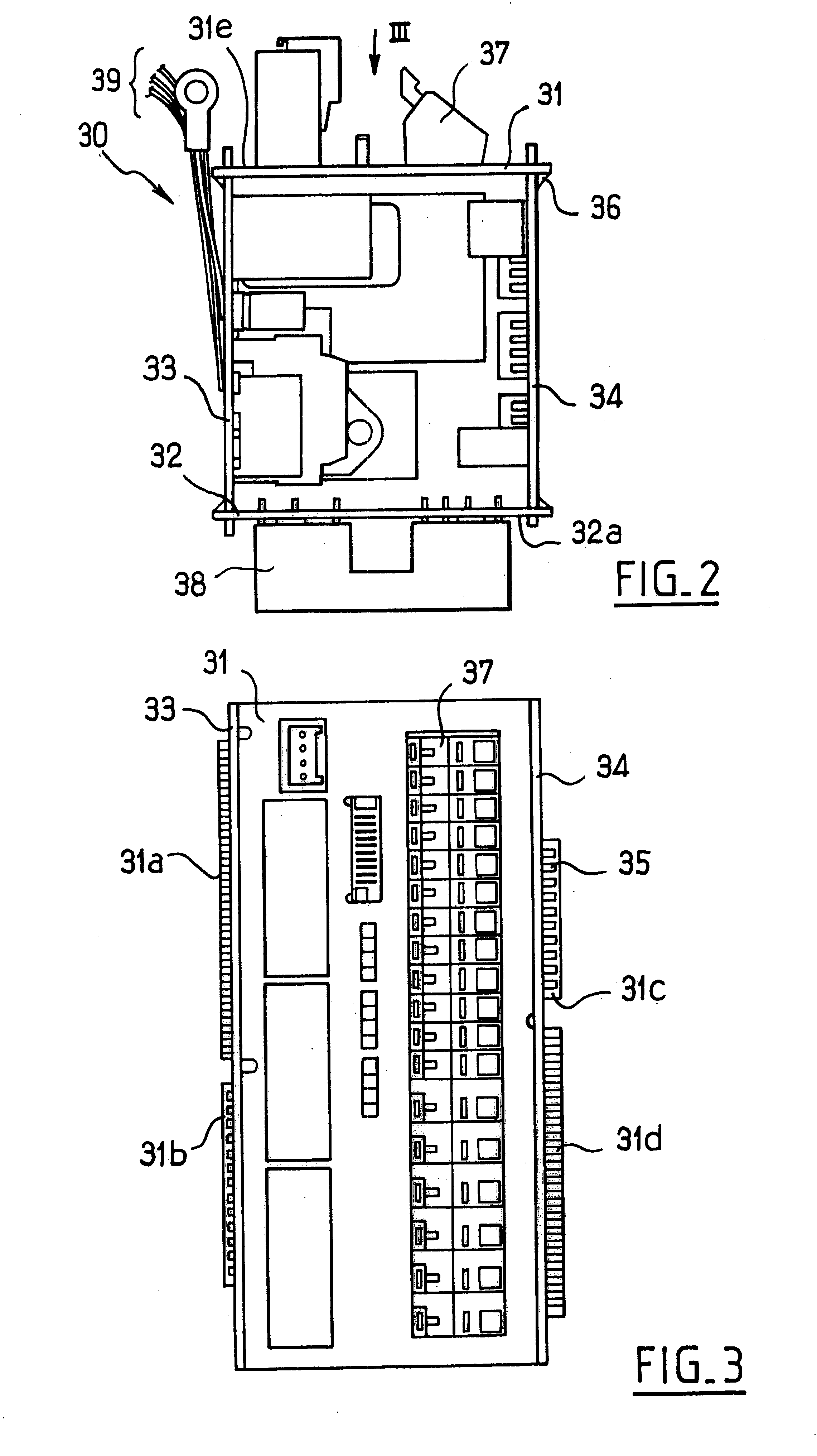
FIG. 2 shows the set of electronic cards 30 in isolation.

The front and rear cards 31 and 32 are parallel and perpendicular to the intermediate cards 33 and 34.

In the vicinity of their ends adjacent to the front and rear cards 31 and 32, the intermediate cards 33 and 34 are provided with slots, while the front and rear cards 31 and 32 are provided with connection tongues shaped to engage in the above-mentioned slots.

The connection tongues of the front card 31 carry references 31a to 31d in FIG. 3.

Conductor tracks 35 are made on the connection tongues, said tra...


PUM


Abstract

A converter for an electric motor or transformer, the converter being comprising a connection box having passages for electrical conductors and having a semiconductor electronic module removably fixed to the connection box. The electronic module has a radiator-forming box that is open at one end, at least one electronic card at least partially embedded in a resin cast inside said radiator-forming box, and at least one connector emerging from the resin. The opening of the radiator-forming box enables it to be fitted to the connection box. The connection box has at least one window giving access to the connector(s) of the electronic module.

Description

The present invention relates to a converter for an electric motor or a transformer and more particularly but not exclusively a converter for a motor that is asynchronous or synchronous, that has permanent magnets, or that operates on DC.The term "converter" is used to cover inverters and drives, i.e. any static semiconductor apparatus enabling an electric motor to be controlled or frequency to be changed when feeding an electric transformer.Converters are known that comprise electronic cards received in a box fixed on the motor.The drawback of such known converters is that in the event of an electronic failure, it is necessary to replace the entire box, which means that the box must be separated from the motor.Furthermore, each box is specific to a given motor which gives rise to relatively high manufacturing costs when a motor is made in a short manufacturing run only.OBJECTS AND SUMMARY OF THE INVENTIONThe invention seeks to provide a novel converter which makes it possible in pa...

Claims


Application Information

Patent Timeline
Patent Type & Authority Patents(United States)
IPC IPC(8): H02K5/04H02K5/18H02K11/04H02K5/22H02K11/33
CPCH02K5/18H02K11/0073H02K5/225H02K11/33
Inventor PETIT, SERGEPETILLON, JEAN-MARCBUISSON, ALAINGIRAUD, REGIS
Owner MOTEURS LEROY SOMER
Why Eureka
Try Eureka