Method and apparatus for applying decimation processing to vehicle position data based upon data accuracy estimation

a vehicle position and data accuracy technology, applied in the field of mobile body navigation apparatuses, can solve the problems of insufficient precision of accident site position, excessive time required to notify the necessary information to an emergency vehicle dispatch center, and substantial amount of time required for transmitting the necessary data

Inactive Publication Date: 2002-11-12
PANASONIC CORP
View PDF9 Cites 39 Cited by
  • Summary
  • Abstract
  • Description
  • Claims
  • Application Information

AI Technical Summary

Benefits of technology

It is a second objective of the invention to provide a position data decimation method and position data decimation apparatus for use with a vehicle navigation apparatus having a capability for radio transmission of position data expressing a traversed route, whereby the amount of data required to be transmitted for expressing all or part of a route traversed by the vehicle can be substantially reduced.
In that way, by ensuring that only position data having a sufficiently high level of accuracy is stored in memory, for use in subsequently generating a display of the vehicle's traversed route, the amount of data which must be stored in order to record a traversed route portion can be substantially reduced.
In that way, by ensuring that only position data having a sufficiently high level of accuracy are transmitted by radio, expressing a portion of the vehicle's traversed route, the amount of data which must be transmitted can be substantially reduced, and hence the route data can be transmitted within a shorter period of time.
To achieve the second objective, according to a ninth aspect of the invention, the degree of precision of the route data is increased for a portion of the traversed route which is close to a desired final position, by comparison with portions of the traversed route which are more distant from the desired final position. Specifically, each of the derived vehicle positions is recorded in conjunction with the distance which the vehicle has moved since the preceding position was obtained. If it is subsequently required to transmit a portion of the traversed route, a set of successively obtained positions which extend to a specific cumulative distance from the current position, are each transmitted. A second set of successively obtained positions (extending from the farthest position of the first set), are then selected, and only a proportion of these are transmitted, for example every second position. This principal can be extended to one or more other sets of successively obtained positions, with the proportion of the contents of each set that are actually transmitted being reduced in accordance with distance from the final position of the vehicle. In that way, the final portion of the traversed route can be expressed with a high degree of precision by the transmitted data, while ensuring that the total amount of transmitted data can be reduced.

Problems solved by technology

If only data expressing a single position (i.e., the approximate final position of the vehicle) are transmitted to the emergency services center, it may not be possible for the position of the accident site to be specified with sufficient precision.
However due to the large amount of data which are necessary to express such a traversed route, a substantial amount of time will be required to transmit the necessary data.
Hence, the problem arises that the time required to notify the necessary information to an emergency vehicle dispatch center may be excessively long.
Conversely, if it is attempted to overcome this problem by transmitting only a small amount of position data, then it becomes difficult for the emergency vehicle dispatch staff to accurately judge the actual position of the accident site, so that effective dispatch of assistance may not be possible.
For each of these vehicle positions, if the total number of satellites is judged to be insufficient, then this considered to indicate that the accuracy of the obtained position information is insufficient, and the position transmission judgement means prevents the corresponding position data from being transmitted.

Method used


Image

  • Method and apparatus for applying decimation processing to vehicle position data based upon data accuracy estimation
  • Method and apparatus for applying decimation processing to vehicle position data based upon data accuracy estimation
  • Method and apparatus for applying decimation processing to vehicle position data based upon data accuracy estimation

Examples


second embodiment

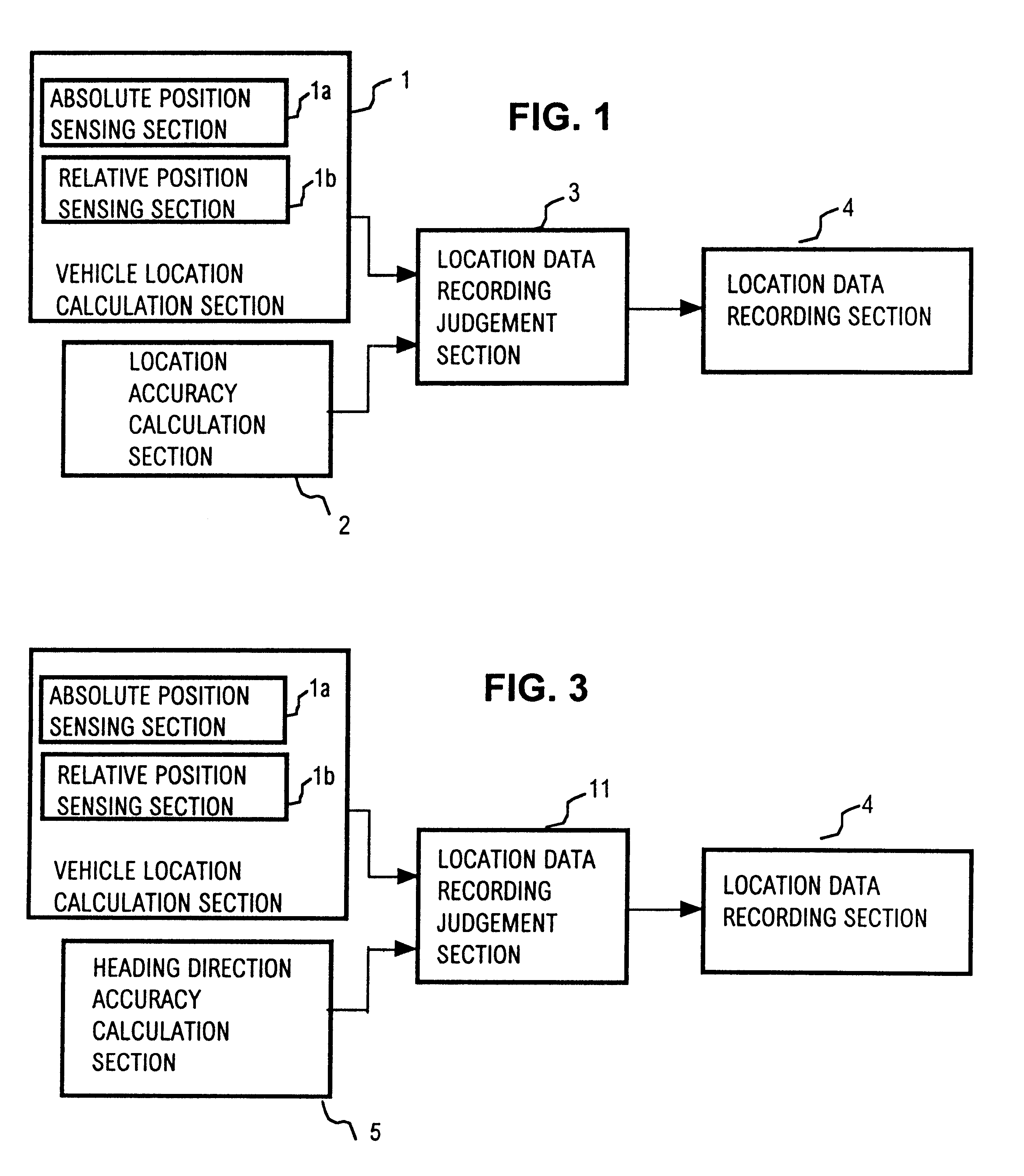
A second embodiment will be described referring to the general system block diagram of FIG. 3 and the corresponding basic flow diagram of FIG. 4. This embodiment essentially differs from the preceding embodiment in that a navigation satellite number calculation section 6 is utilized in place of the position accuracy calculation section 2 of the first embodiment, while the respective functions of the vehicle position calculation section 1, position data recording judgement section 11 and position data recording section 4 substantially correspond to those of vehicle position calculation section 1, position data recording judgement section 3 and position data recording section 4 of the first embodiment. With this embodiment, the aforementioned absolute position sensing section of the vehicle position calculation section 1 derives, in conjunction with each absolute position, a corresponding absolute heading direction of the vehicle. Similarly, the aforementioned relative position sensin...

third embodiment

A third embodiment will be described referring to the general system block diagram of FIG. 5 and the corresponding basic flow diagram of FIG. 6. This embodiment essentially differs from the first embodiment in that a navigation satellite number calculation section 6 is utilized in place of the position accuracy calculation section 2 of the first embodiment, while the respective functions of the vehicle position calculation section 1, position data recording judgement section 12 and position data recording section 4 substantially correspond to those of the vehicle position calculation section 1, position data recording judgement section 3 and position data recording section 4 of the first embodiment.

With this embodiment, each time that the current position of the vehicle is newly calculated by the vehicle position calculation section 1, with the resultant position data being transferred to the position data recording judgement section 12, the navigation satellite number calculation s...

fourth embodiment

A fourth embodiment will be described referring to the general system block diagram of FIG. 7 and the corresponding basic flow diagram of FIG. 8. This embodiment essentially differs from the first embodiment in that a calculation status detection section 7 is utilized in place of the position accuracy calculation section 2 of the first embodiment, while the respective functions and operation of the vehicle position calculation section 1, position data recording judgement section 13 and position data recording section 4 substantially correspond to those of the vehicle position calculation section 1, position data recording judgement section 3 and position data recording section 4 of the first embodiment.

With this embodiment, each time that the position of the vehicle is newly calculated by the vehicle position calculation section 1, the position calculation status detection section 7 derives satellite acquisition status information which specifies whether or not GPS information was s...


PUM


Abstract

A method and apparatus for use with a mobile body navigation system are provided for reducing an amount of position data, expressing successive positions along a route that has been traversed by a mobile body, which are recorded by a data recording section to subsequently provide a route display or are transmitted by radio by a data transmitting section. A position recording judgement section uses one or more judgement criteria to obtain an indication of the degree of accuracy of each of the vehicle positions that are calculated by the navigation system, and enables recording or transmission of only those data that express positions for which the judgement criteria indicate that the corresponding degree of accuracy is sufficiently high.

Description

1. Field of the InventionThe present invention relates to an improvement of a mobile body navigation apparatus having a capability for recording and displaying position data representing all or part of a route which has been traversed by a mobile body such as a motor vehicle, or for transmitting position data representing the traversed route and current position by radio in the event of an emergency.2. Description of the Prior ArtPrior art types of navigation apparatus for mounting on a mobile body such as a motor vehicle are known, having a traversed route display function for displaying at least a part of the route which has been traversed by the vehicle. Successively calculated sets of position data for generating this traversed route display, i.e., data expressing successively attained positions of the vehicle, are recorded temporarily in a data storage device, and read out therefrom for use in generating the route display. The present invention relates in particular to a hybrid...

Claims


Application Information

Patent Timeline
Patent Type & Authority Patents(United States)
IPC IPC(8): G01C21/26G01C21/00G01B21/00G01S19/48G07C5/00G08B21/00G08G1/0969
CPCG01C21/26
Inventor MIZUNO, MASARU
Owner PANASONIC CORP
Why Eureka
Try Eureka