Removal apparatus for molded product and method for removing molded products

a technology for removing equipment and products, applied in the direction of dough shaping, application, manufacturing tools, etc., can solve the problems of large size and heavyness of the conventional removal apparatus for removing molded products

Inactive Publication Date: 2002-11-26
STAR SEIKI
View PDF11 Cites 59 Cited by
  • Summary
  • Abstract
  • Description
  • Claims
  • Application Information

AI Technical Summary

Problems solved by technology

As a result, the conventional removal apparatus

Method used


Image

  • Removal apparatus for molded product and method for removing molded products
  • Removal apparatus for molded product and method for removing molded products
  • Removal apparatus for molded product and method for removing molded products

Examples


Embodiment Construction

Hereinafter, a description is given of preferred embodiments of the invention with reference to the accompanying drawings;

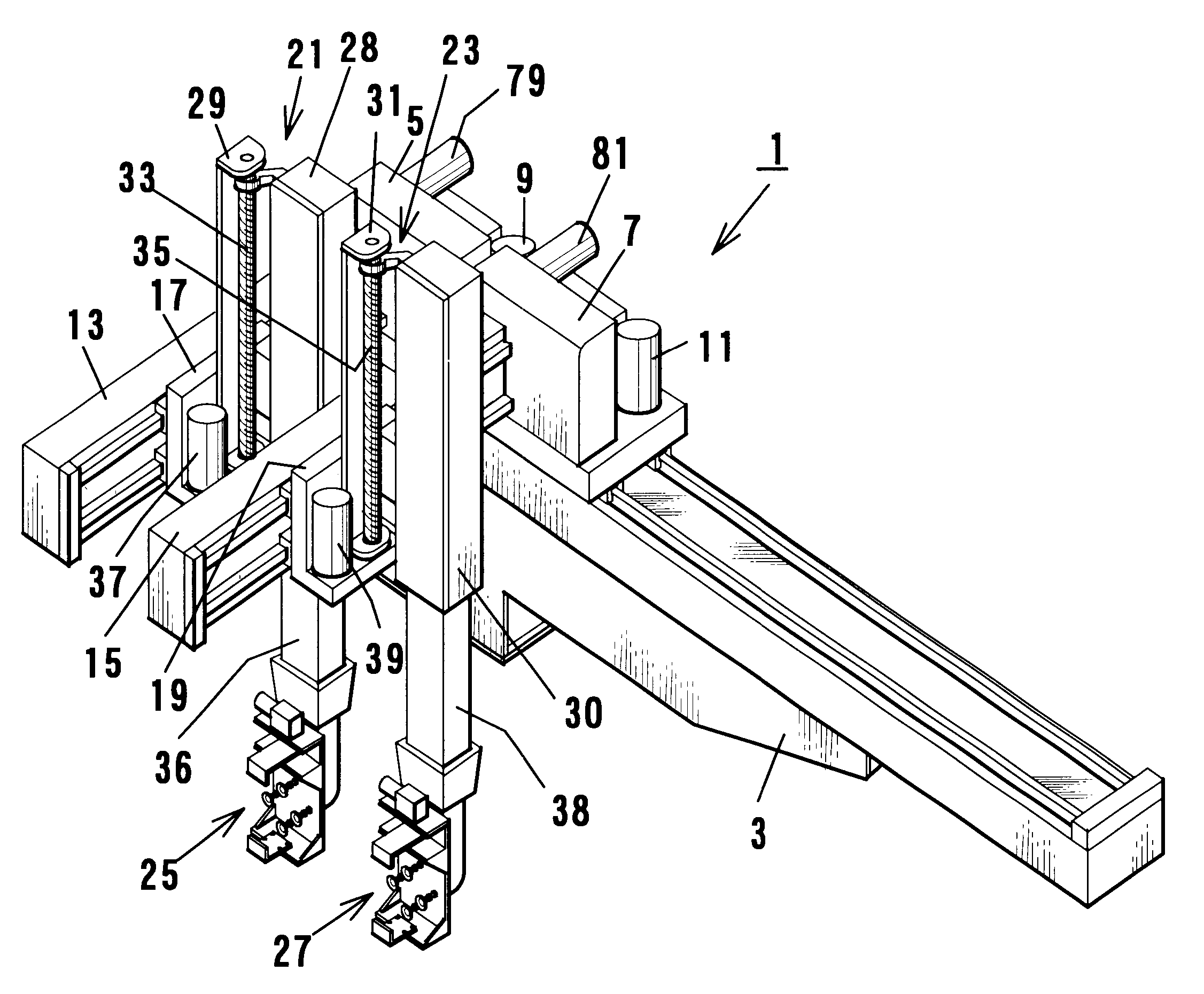
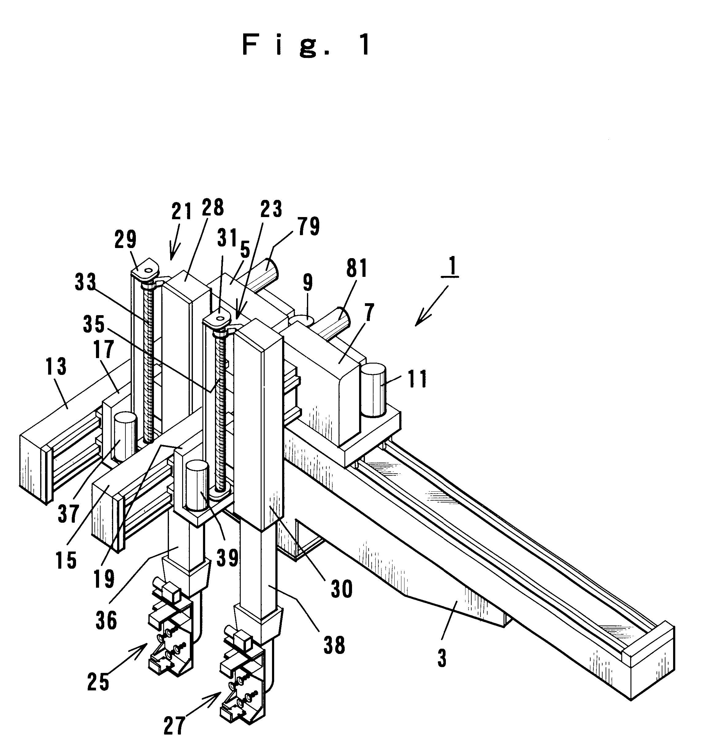
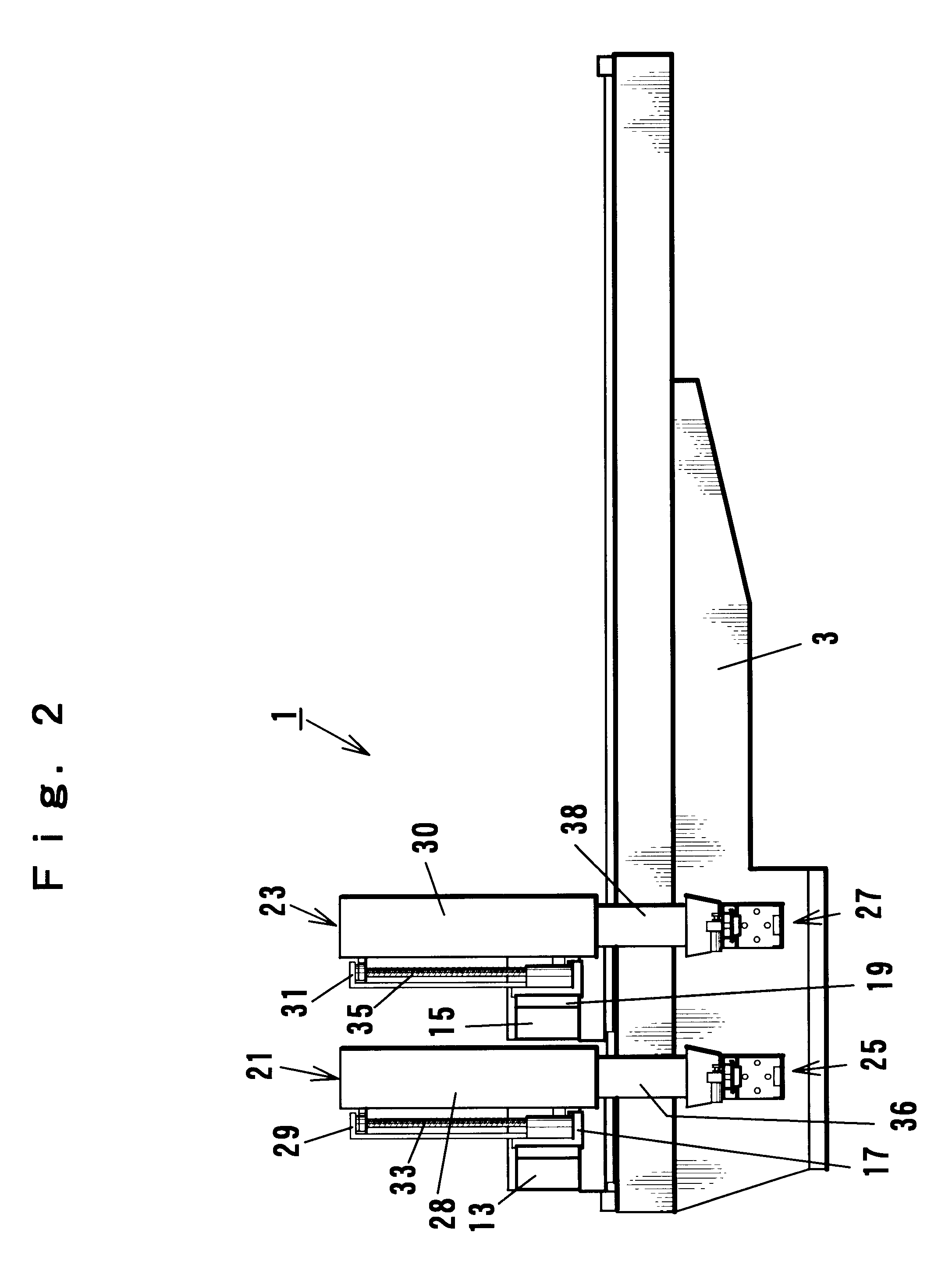
Referring to FIG. 1 through FIG. 4, a travelling frame 3 of a removal apparatus for molded product has a base portion fixed on the upper part of a fixed surface plate 2 of a molding machine. In the longitudinal direction, the travelling frame 3 has a length bridging from the upper part of a molding section of the molding machine to a release position at the side of the molding machine. The first and second carriages 5 and 7, respectively, are supported on the travelling frame 3 so as to independently reciprocate in the longitudinal direction. And the first and second carriages 5 and 7 are, respectively, provided with first and second cross frames 13 and 15 extending in the cross direction.

As a drive mechanism to cause the first and second carriages 5 and 7 to reciprocate, a rack and pinion drive mechanism is employed, wherein the rack and pinion drive mechanism c...


PUM

PropertyMeasurementUnit
Lengthaaaaaaaaaa

Abstract

A removal apparatus is provided which includes a travelling frame, first and second carriages provided on the travelling frame, first and second cross frames provided on the first and second carriages, first and second cross carriages provided on the first and second cross frames, first and second vertical units provided on the first and second cross carriages, and first and second chucking units secured to the first and second vertical units. In addition, a control unit is provided for synchronously controlling the movement of the first and second carriages, the first and second cross carriages, and the first and second vertical units so as to enable the first and second chucking units to be moved in three dimensions for removal of a molded product from a molding machine.

Description

1. Field of the InventionThe present invention relates to a removal apparatus for molded product and a method for removing molded products.2. Background of the InventionIn the prior arts, a removal apparatus for molded product, which takes out molded products by moving and controlling a chuck portion in three-dimensional directions, has been already known, wherein the apparatus is provided with a cross travelling carriage supported so that it reciprocates in the axial direction (cross direction) of a molding machine on a cross frame of a carriage reciprocating in a direction (longitudinal direction) orthogonal to the axial line of the molding machine on a travelling frame fixed on a fixed surface plate of the molding machine, and a vertical unit which moves a chuck portion for holding molded products in the vertical direction.It is necessary to attach a large-sized chucking portion that is capable of holding large-sized products, in order to remove large-sized products such as a bum...

Claims


Application Information

Patent Timeline
IPC IPC(8): B29C45/42B29C43/50B29C43/32
CPCB29C45/42B29C43/50B29C2043/5061B29C2043/5069B29C2045/7633
Inventor SHIOTANI, YOUSUKE
Owner STAR SEIKI
Why Eureka
Try Eureka