
Equipment for calcination

Inactive Publication Date: 2002-11-26
PSP EHNZHINEERING AS
View PDF3 Cites 12 Cited by
  • Summary
  • Abstract
  • Description
  • Claims
  • Application Information

AI Technical Summary

Benefits of technology

Using a construction according to the invention a better efficiency of calcinating equipment in whole is achieved and this at a lesser energy consumption. This is then manifested in decreasing investment and operation costs to unit of production.

Problems solved by technology

The disadvantage of such type of calcinating equipment is the relatively high pressure energy loss of entering gases, caused by the necessity of sometimes multifold lifting of powdered material, especially in case when in the calcinating chamber a greater amount of material is retained, as it would be necessary for the desired calcination level.
But the powdered material at this construction version has not an other possibility, as to fall in direction of the gravitation forces that means downwards.
So the time of staying of powdered material in the calcinating chamber of this type is relatively short, what deteriorates the possibility of its thermal processing that means the level of calcination.
The effort for intensive swirling of powdered material leads additionally to increase of the pressure loss of hot burning air, which is led into the calcinating chamber for instance from the following clinker cooler.
The mentioned disadvantages have as consequence the worsening of technological process effectiveness and the increasing of investment and operation costs for unit of production.

Method used


Image

  • Equipment for calcination
  • Equipment for calcination
  • Equipment for calcination

Examples


Embodiment Construction

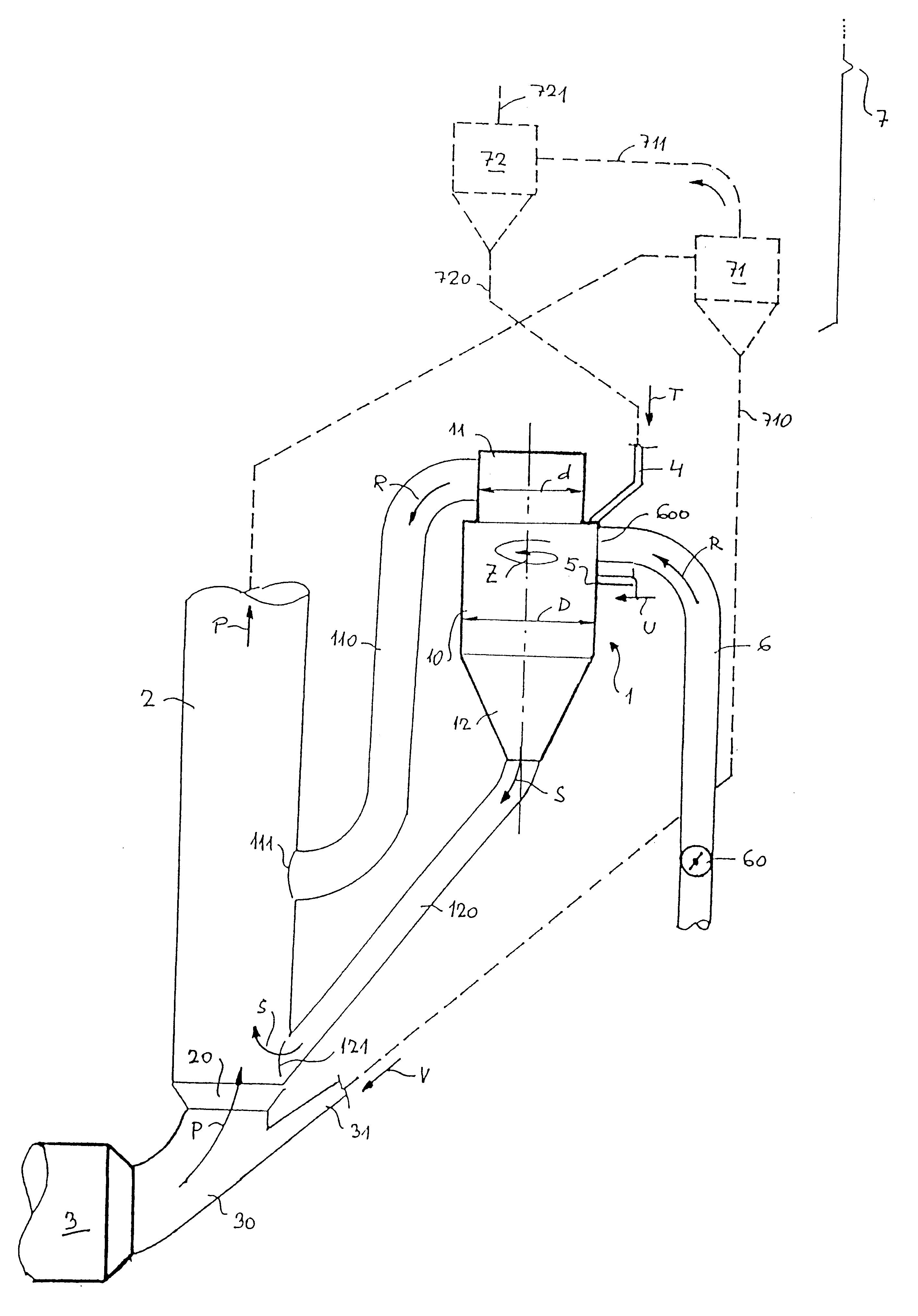
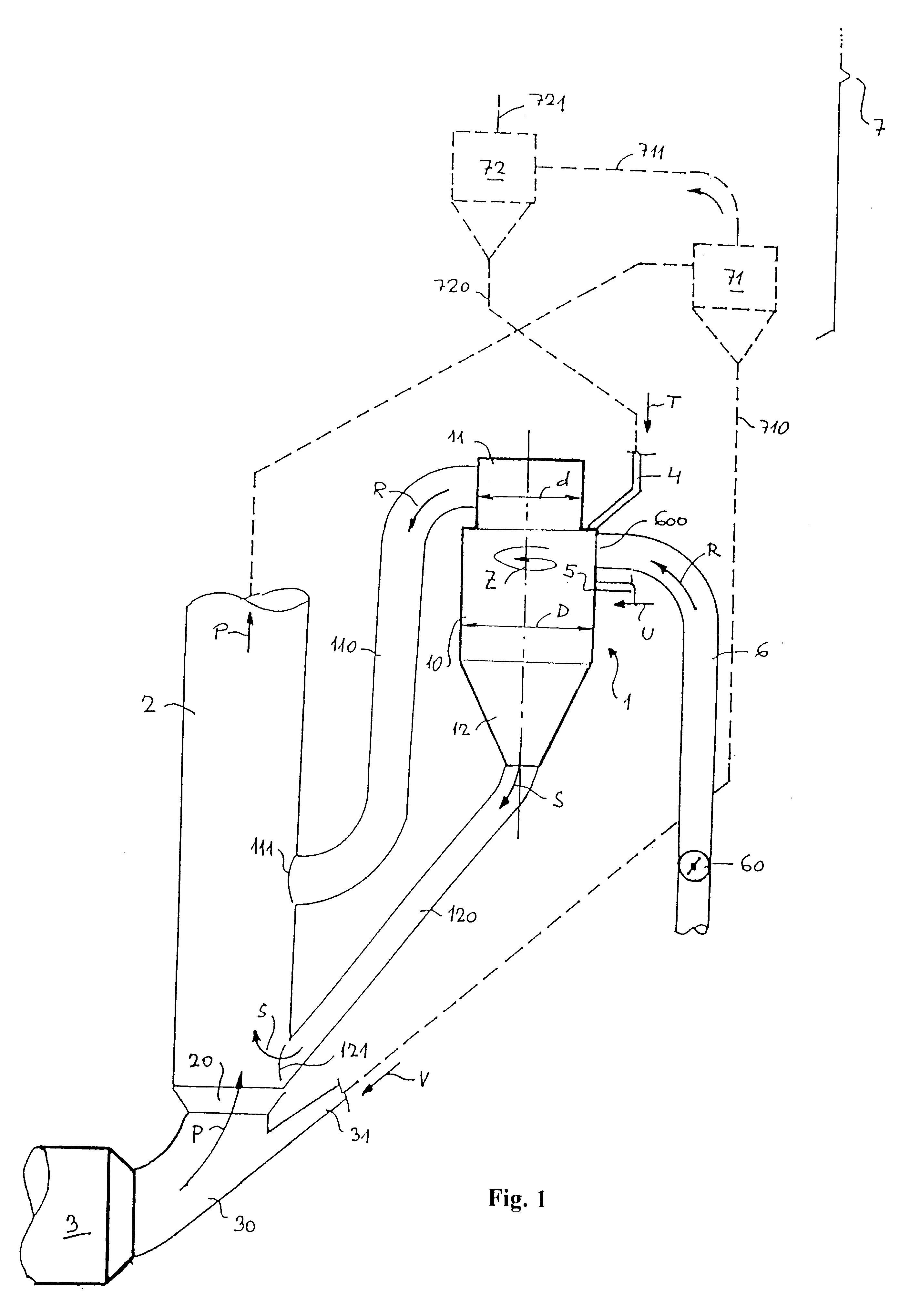
The calcinating equipment according to the invention demonstrated on the FIG. 1 in an example embodiment is a part of a technological unit, which is composed from one the one hand a rotary kiln 3 with input chamber 30 and input tube 31 of powdered material and on the other hand from a cyclone type exchanger 7, which is designed for preheating of powdered material processed subsequently in rotary kiln 3 where the preheater lower part is shown on the FIG. 1 with dash line. On this FIG. the two lowest cyclones are shown in dash lines, and this the last cyclone 71 with the output tube 710 of powdered material and with the removal tube 711 of hot gas and the last but one cyclone 72 with the output tube 720 of powdered material and with the removal tube 721 of hot gas. The last cyclone 71 and the last but one cyclone 72 are mutually interconnected with the removal tube 711.

As it is shown on the FIG. 1, the calcinating chamber 1 according to the invention is composed from a middle position...


PUM


Abstract

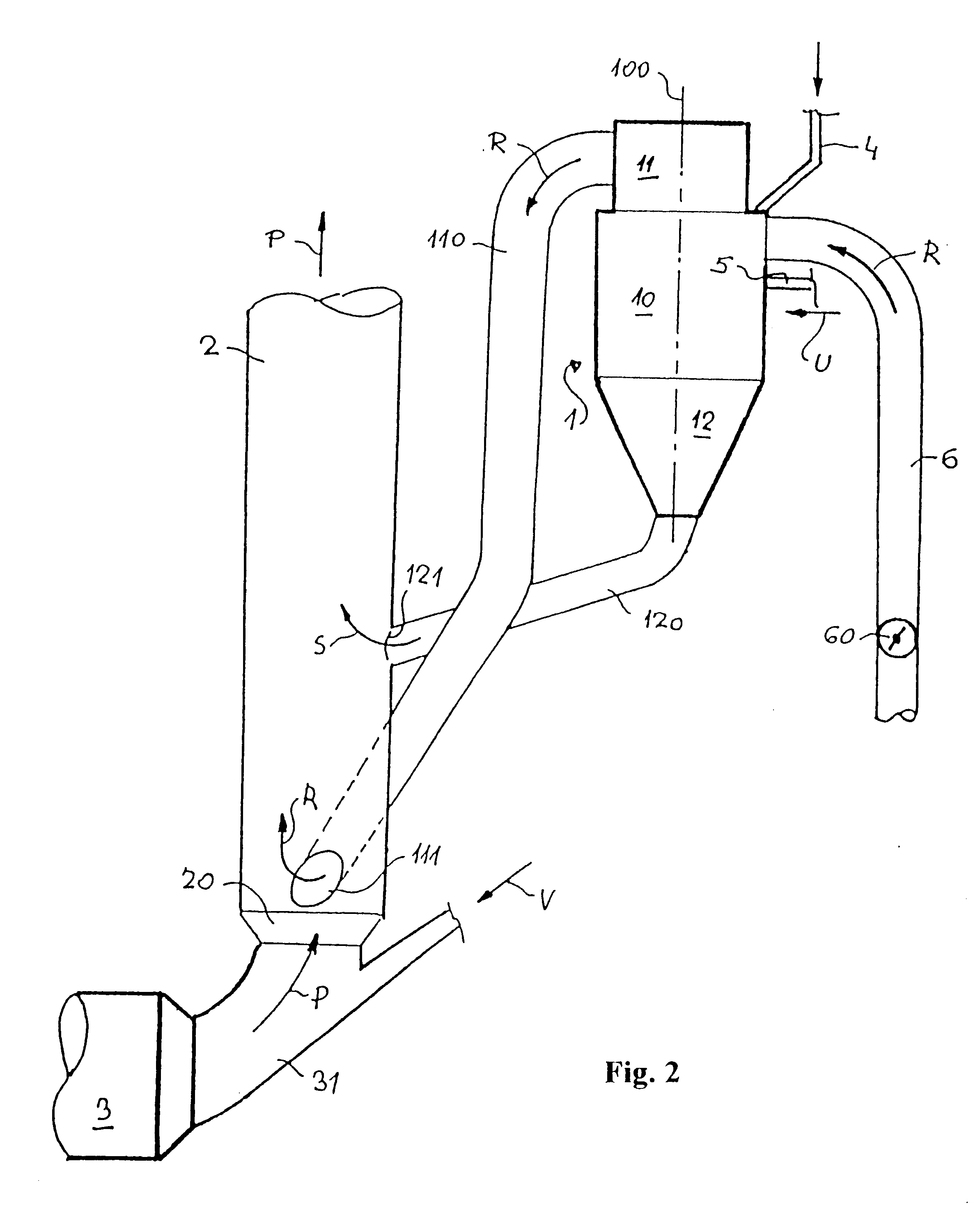
An equipment for calcination for precalcining of powdered materials before their burning in a sintering equipment is inserted between the last but one cyclone (72) of connected cyclone exchanger (7) and the mixing channel (2), arranged over the input chamber (31) of connected rotary kiln (3) and connected to the input to the last cyclone (71) of cyclone exchanger (7) and it is composed from calcinating chamber (1), which have three parts-a working part (10), to which are connected the at least one air tube (6) and the at least one fuel input (5) and where this working part (10) and / or air tube (6) are further provided with input (4) of powdered material, and the upper part (11), which is provided with at least one interconnecting tube (110) serving for interconnecting with mixing channel (2) and lower part (12), which is provided with a removal tube (120) for interconnecting with the mixing channel (2). There is an input (4) of powdered material into the air tube (6) close to its mouth (600) to the calcinating chamber (1), eventually there is an auxiliary input (41) of powdered material and an auxiliary fuel input (51) additionally added into the air tube (6). Also the mixing channel (2) is advantageously equipped with additional input (42) of powdered material and with it connected additional fuel input (52) and with additional air tube (62).

Description

The invention deals with an equipment for calcination for precalcining of powdered materials before their burning in a sintering equipment, namely of cement raw material farina before its burning in a rotary kiln, composed from a calcinating chamber, which is provided with means for input of powdered material and input of fuel with a simultaneous input of burning air and which is interconnected with a mixing channel, which is arranged between the input chamber of rotary kiln and the last cyclone of cyclone heat exchanger which is arranged before the rotary kiln.THE PRIOR ARTRecently the material at a lot of used equipment with calcinating chambers for calcination of powdered materials, for instance of cement raw material farina, led usually to the lower part of calcinating chamber. To this area also the hot gases from one or more heat sources are led, for instance for clinker cooler, or from the rotary kiln. The powdered material is by the influence of the entering gases kinetic ene...

Claims


Application Information

Patent Timeline
IPC IPC(8): C04B7/00C04B7/43F27B7/20F26B17/22
CPCC04B7/434F27B7/2033Y02P40/121
Inventor POSPISIL, JAROSLAVZAJDLIK, JOSEFMICHALEK, ZDENEKKREJCI, PETRPUMPRLA, ALOISSEHNALEK, ALOIS
Owner PSP EHNZHINEERING AS
Learn More