Optical engine and an image projector having the optical engine

an image projector and optical engine technology, applied in the field of optical engines, can solve the problems of high energy consumption and mass of the optical engine, and achieve the effects of reducing the dispersion angle of light, increasing the cross-sectional size, and uniformizing the ligh

Inactive Publication Date: 2006-04-13
PREMIER IMAGE TECH
View PDF3 Cites 24 Cited by
  • Summary
  • Abstract
  • Description
  • Claims
  • Application Information

AI Technical Summary

Benefits of technology

[0009] In accordance with one aspect of the present invention, an optical engine is provided, which comprises: a light source, a taper rod, at least one light condenser, a prism module, a Digital Micromirror Device (DMD) And a projection lens set. One end of the taper rod is adjacent to the light source. Light generated by the light source is guided by the taper rod following a light path. The taper rod has increasing sizes of cross-sections along the light path, so as to decrease the di

Problems solved by technology

This is one of the main reasons that results in a higher

Method used


Image

  • Optical engine and an image projector having the optical engine
  • Optical engine and an image projector having the optical engine
  • Optical engine and an image projector having the optical engine

Examples


first embodiment

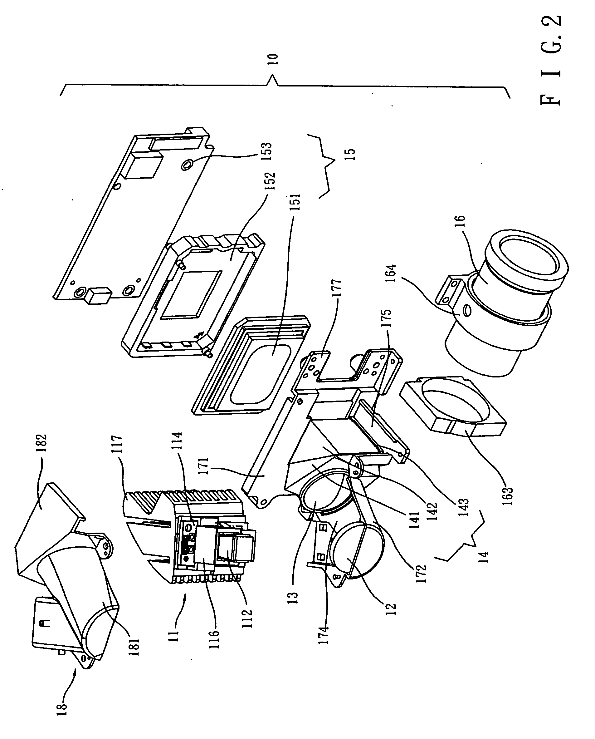
[0034]FIG. 8 is a similar exploding diagram to FIG. 2 which shows an illuminator module 11 of the optical engine 10 according to the invention. This illuminator module 11 includes a light source 111, a taper rod 112, light reflection piece, a PCB 114, a fixing column 115 and a spring clip 116. This illuminator module 11 also combines a heat-dissipating component 117 to dissipate heat.

[0035] Light source 111 is set to emit light ray toward in the direction of a predetermined light axis. In an embodiment, light source 111 is a light emitting diode (LED). The taper rod 112 is adjacent to light source 111. The taper rod 112 includes a plurality of narrow and long surfaces 1121 along the extended direction of the light source. The perpendicular cross-sectional surface of the taper rod 112 and the light axis forms a polygon in this way. Each of narrow and long surfaces 1121 has two corresponding long edges 1122 and 1123 that generally extend along the direction of the light source and two...

second embodiment

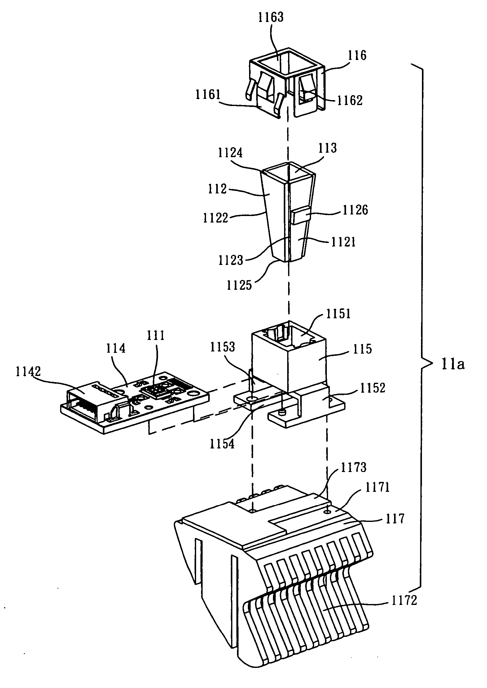
[0042]FIG. 10 illustrates a block diagram of the illuminator module 11a of the optical engine according to the invention. The illuminator module 11a shown here in FIG. 10 is similar to the illuminator module 11 shown in FIG. 8 in that, it also includes: light source 111 (light emitting diode, LED), taper rod 112a, light reflection piece, PCB module 114, a fixing stand 115a and a spring clip 116. It also has a heat dissipating element 117 to dissipate heat. The difference in illuminator module 11a is that it has a hollow oriented casing 118 and at the end of the larger cross-sectional area of the taper rod 112a, there is a bulging edge 1127. The taper rod 112a is transfixed into the hollow oriented casing 118 so that the bulging edge 1127 is fixed on the upper and inner fold 1181 of the hollow oriented casing 118. The other end of the casing 118 is fixed to the PCB module 114 and the fixing stand 115a through connecting element 1182. The taper rod 112a is a solid pyramid. There are l...

third embodiment

[0043]FIG. 11 illustrates a block diagram of the illuminator module 11b. According to FIG. 11, illuminator module 11b is similar to illuminator module 11a in general. It also includes: a light source 111 (light emitting diode), taper rod 112b, a light reflection piece, PCB 114, a fixing stand 115b, a spring clip 116 and an oriented casing 118b. The difference between the two illuminator modules is that the bulging edge 1127b of the taper rod 112b is an independent part from the taper rod and it is made of a transparent piece-like material (e.g. Glass or acrylic resin) whose size is a bit larger than the larger cross-sectional surface of the taper rod 112b. Besides, the bulging edge is glued to the pole 112b.

[0044]FIG. 12 shows the combination diagram of the heat dissipating element 117 to the illuminator module 11b shown in FIG. 11.

[0045]FIG. 13 shows the combination diagram of the base 17, the concave mirror 12, the converging lens 13 and the prism set 14 to the illuminator modul...


PUM


Abstract

An optical engine for an image projector comprises a light source, a taper rod, at least one light condenser, a prism module, a Digital Micromirror Device (DMD) and a projection lens set. One end of the taper rod is adjacent to the light source. Light generated by the light source is guided by the taper rod following a light path. The taper rod has increasing sizes of cross-sections along the light path, so as to decrease the dispersion angle of light, make the light more uniform, and increase the brightness of light. The prism module includes a first prism having a right triangle cross-section and a second prism having a wedge cross-section. The prism module receives the light from the condenser, passes the light toward the DMD, receives the light reflected by the DMD, and then passes the reflected light toward the projection lens set. The projection lens set projects the light on an external projection plane.

Description

BACKGROUND OF INVENTION [0001] 1. Field of the Invention [0002] This invention is related to an optical engine. In particular, this invention is related to an optical engine located in an image projector comprising a light source, at least one light condenser, a prism module, and a projection lens set. [0003] 2. Description of the Prior Art [0004] The quality of the image is highly related to an internal optical engine for an image projector. To get a better quality of image, the lightness, homogeneity and effectiveness of the light source should be considered into the design of the optical engine. Besides, it is of paramount importance that the light travels through the lenses and prisms should not be deflected so the image gained would not be in disagreement with the real one. No less important is the dimness of the light that will let image ends in vagueness and in low contrast. To emphasize the homogeneity of the light, massive optical lenses, polarized lenses and spectroscopes ...

Claims


Application Information

Patent Timeline
IPC IPC(8): G02B6/10G02B27/09
CPCG02B27/0927G02B27/0994H04N9/315
Inventor WU, CHAO HSIENWANG, YUAN LINPAN, JUI WEN
Owner PREMIER IMAGE TECH
Why Eureka
Try Eureka