
Methods and systems for increasing the carbon content of sponge iron in a reduction furnace

Active Publication Date: 2017-03-02
MIDREX TECH INC
View PDF11 Cites 2 Cited by
  • Summary
  • Abstract
  • Description
  • Claims
  • Application Information

AI Technical Summary

Benefits of technology

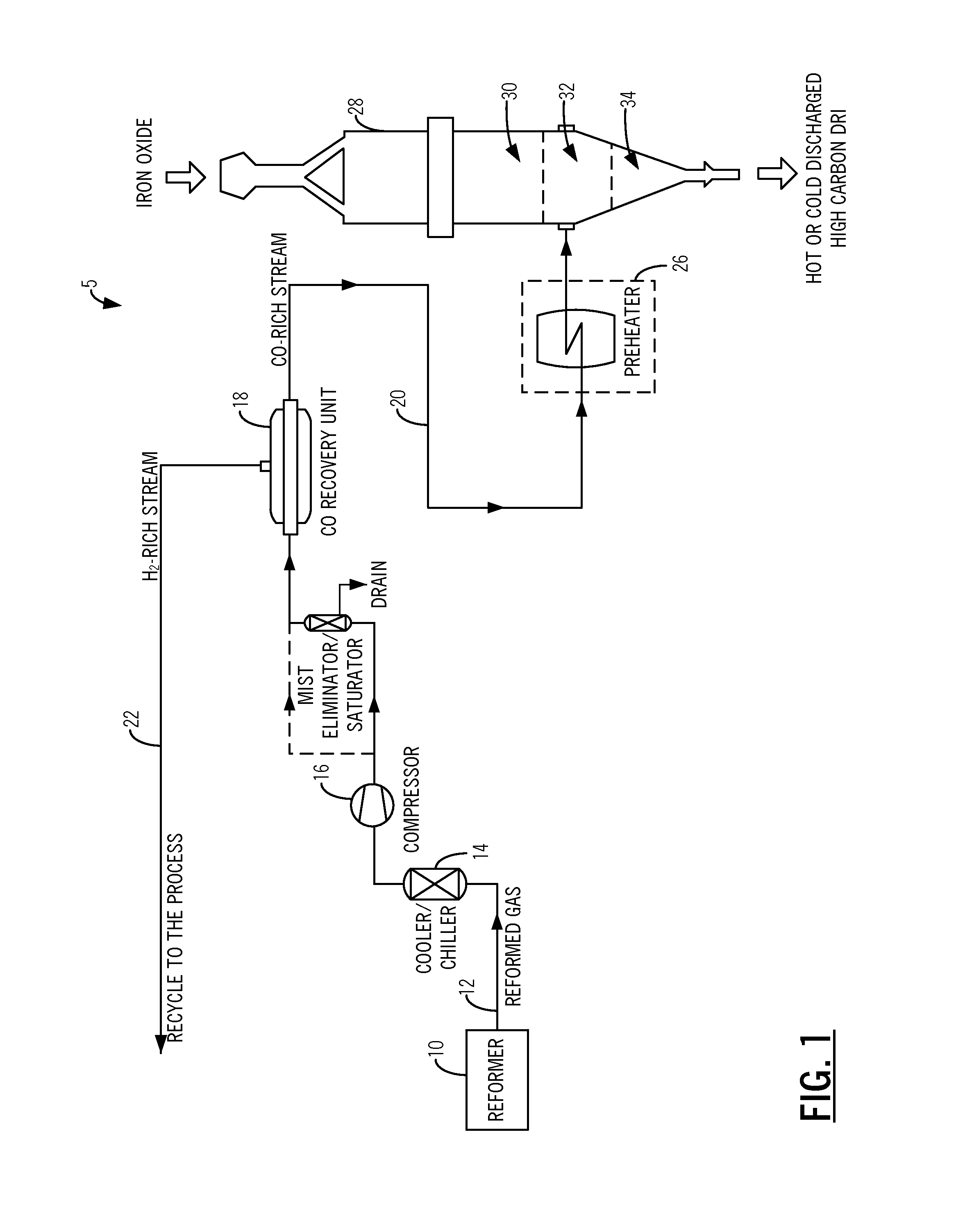
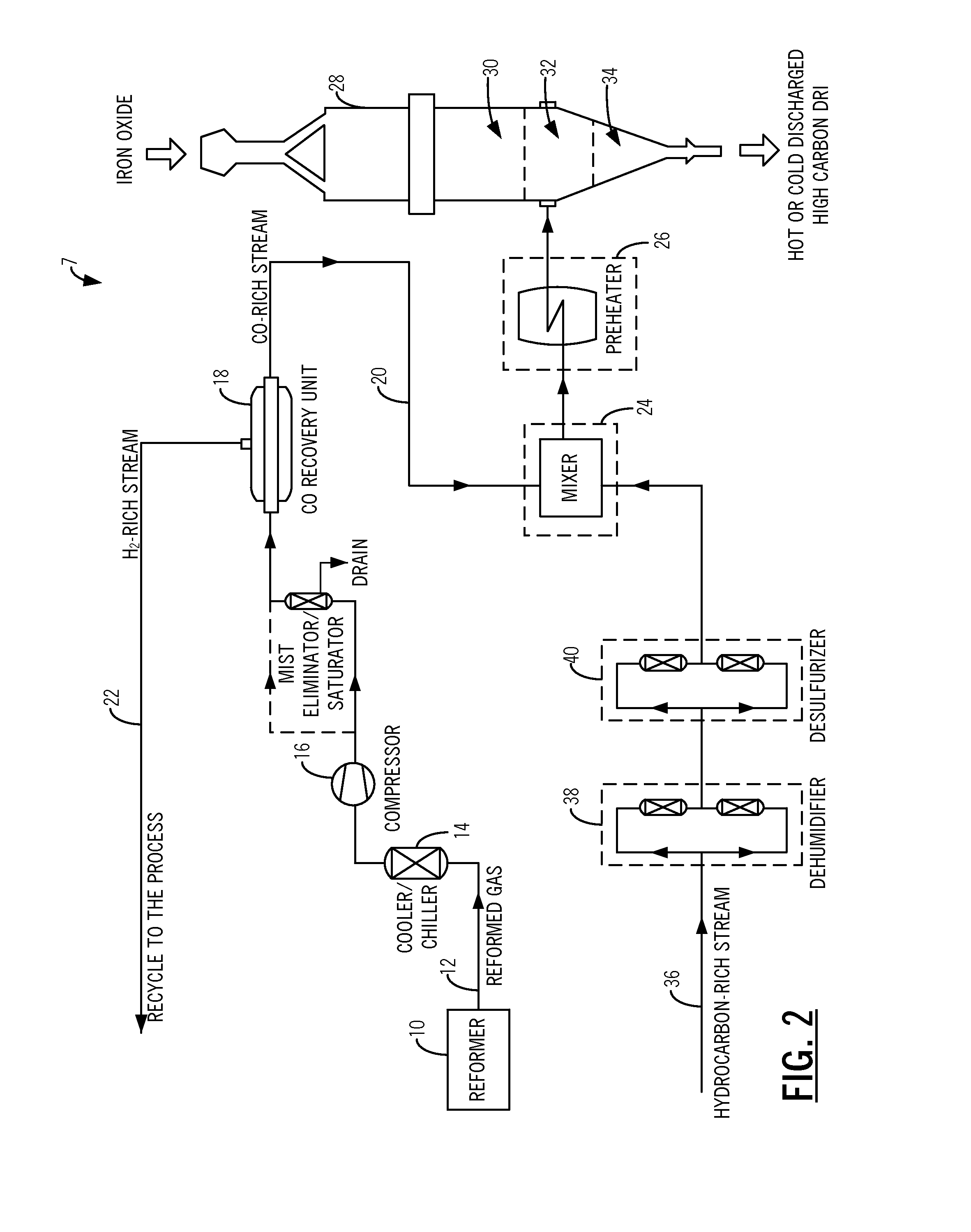
The present invention provides a method for producing direct reduced iron with increased carbon content. This is achieved by delivering a reformed gas stream to a carbon monoxide recovery unit to form a carbon monoxide-rich gas stream and a hydrogen-rich gas stream, which is then exposed to partially or completely reduced iron oxide in a direct reduction furnace. The carbon monoxide-rich gas stream is delivered to one of a transition zone and a cooling zone of the direct reduction furnace. The method also involves cooling the reformed gas stream, compressing it, and recycling the hydrogen-rich gas stream for use in a direct reduction plant. The final carburizing gas is formed by mixing the carbon monoxide-rich gas stream with a hydrocarbon-rich gas stream, such as natural gas. This results in direct reduced iron with increased carbon content.

Problems solved by technology

Due to the equilibrium-limited nature of reactions (1) and (2), it is not economical to achieve complete (i.e. 100.0%) reduction within the reduction reactor.
In fact, when the degree of reduction approaches 100.0%, an excessively long residence time inside the reduction reactor is required to remove the remaining oxygen from the partially reacted material.
While the rate of reduction reactions can be increased to some extent by increasing temperature, such temperature increases are limited by the fact that the operating temperature must be kept below the sintering temperature so that clusters are not formed inside the reduction reactor.
Although other carbon sources, like coal or rubber, can be added to the EAF for the same purpose, the resulting yield is significantly less than the combined carbon in the DRI, due to particle blow-off and impurities in the carbon sources.
In other words, from an operational point of view, there are limitations to increasing the amounts of CO and CH4 in the reducing gas stream.
Thus, due to cracking reactions in the transition zone, the carbon content of the product increases.
The resulting carbon from these side reactions creates detrimental consequences for the reforming catalyst, and, therefore, it is a common practice to prevent their occurrence by controlling the operating parameters of the reformer unit.
Based on reactions (1) and (2), the presence of oxidants H2O and CO2 in the reducing gas mixture reduces the efficiency of the reduction reactions.

Method used


Image

  • Methods and systems for increasing the carbon content of sponge iron in a reduction furnace
  • Methods and systems for increasing the carbon content of sponge iron in a reduction furnace
  • Methods and systems for increasing the carbon content of sponge iron in a reduction furnace

Examples


Embodiment Construction

[0025]The present invention provides an efficient and cost effective process for increasing the carbon content of DRI in a reformer-based DR plant. It provides a carbon monoxide-rich stream with limited impurities that is directly injected into the bulk of hot and partially or completely reduced materials inside the reduction furnace, or first blended with other gases (e.g. a hydrocarbon-rich gas stream). The combination of coking reactions noticeably increases the carbon content of the resulting DRI, while keeping the temperature of the bulk high.

[0026]For a DR plant utilizing a reforming step, of any type, the following are the main advantages:[0027]The design is simple and straightforward with respect to engineering, construction, and operation.[0028]The conventional method of injecting a hydrocarbon-rich stream into the reduction furnace increases the carbon content of the material by endothermic hydrocarbon cracking reactions; hence lowering the material temperature. The presen...


PUM

PropertyMeasurementUnit
Fractionaaaaaaaaaa
Fractionaaaaaaaaaa
Fractionaaaaaaaaaa

Abstract

Methods and systems for producing direct reduced iron having increased carbon content, comprising: providing a reformed gas stream from a reformer; delivering the reformed gas stream to a carbon monoxide recovery unit to form a carbon monoxide-rich gas stream and a hydrogen-rich gas stream; and delivering the carbon-monoxide-rich gas stream to a direct reduction furnace and exposing partially or completely reduced iron oxide to the carbon monoxide-rich gas stream to increase the carbon content of resulting direct reduced iron. The carbon monoxide-rich gas stream is delivered to one of a transition zone and a cooling zone of the direct reduction furnace. Optionally, the method further comprises mixing the carbon monoxide-rich gas stream with a hydrocarbon-rich gas stream.

Description

FIELD OF THE INVENTION[0001]The present invention relates generally to methods and systems for increasing the carbon content of sponge iron in a direct reduction (DR) furnace.BACKGROUND OF THE INVENTION[0002]Direct reduced iron (DRI), which is also referred to as sponge iron, is typically produced by the reaction of iron ore in a reactive gas stream containing reducing agents, such as H2 and CO, in a moving bed or vertical shaft reactor. The following are the equilibrium-limited global reactions:Fe2O3+3H22Fe+3H2O   (1)Fe2O3+3CO2Fe+3CO2   (2)[0003]In commercial DR processes, the product DRI still contains unreacted iron oxide, which may be as high as 15.0% by weight. Due to the equilibrium-limited nature of reactions (1) and (2), it is not economical to achieve complete (i.e. 100.0%) reduction within the reduction reactor. In fact, when the degree of reduction approaches 100.0%, an excessively long residence time inside the reduction reactor is required to remove the remaining oxygen...

Claims


Application Information

Patent Timeline
IPC IPC(8): C21B13/00C21B13/02C21B13/14
CPCC21B13/0073C21B13/02C21B13/146C21B13/0086C21B2100/22C21B2100/282C21B2100/42C21B2100/60F27D17/004Y02P10/122Y02P10/134C01B3/02C01B3/50
Inventor MOTAMEDHASHEMI, MIRMOHAMMADYOUSEF
Owner MIDREX TECH INC
Learn More