Lateral injection vertical cavity surface-emitting laser

a laser and cavity surface technology, applied in semiconductor lasers, laser details, optical resonator shape and construction, etc., can solve the problems of increasing the rise of the laser, and affecting the accuracy of the laser

Inactive Publication Date: 2002-12-10
LUCENT TECH INC
View PDF7 Cites 31 Cited by
  • Summary
  • Abstract
  • Description
  • Claims
  • Application Information

AI Technical Summary

Problems solved by technology

This conclusion is flawed since it focuses on only the direct current paths through the aperture and neglects parallel paths through which the current flows.
In addition, the speed of operation of prior art lateral injection VCSELs, including those of Creusen, is limited by parasitic capacitance.
The higher capacitance increases the RC time constant of these lasers and, therefore, increases their rise and fall time when they are turned on and off, which in turn limits their modulation speed.

Method used


Image

  • Lateral injection vertical cavity surface-emitting laser
  • Lateral injection vertical cavity surface-emitting laser
  • Lateral injection vertical cavity surface-emitting laser

Examples


example

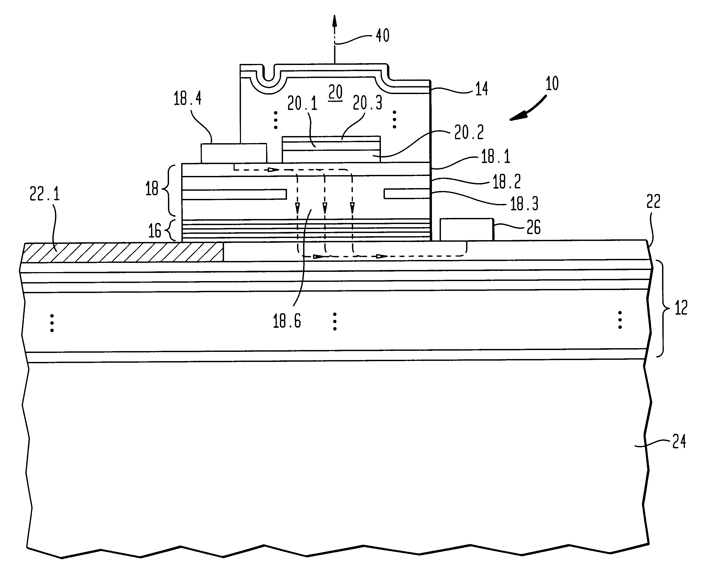
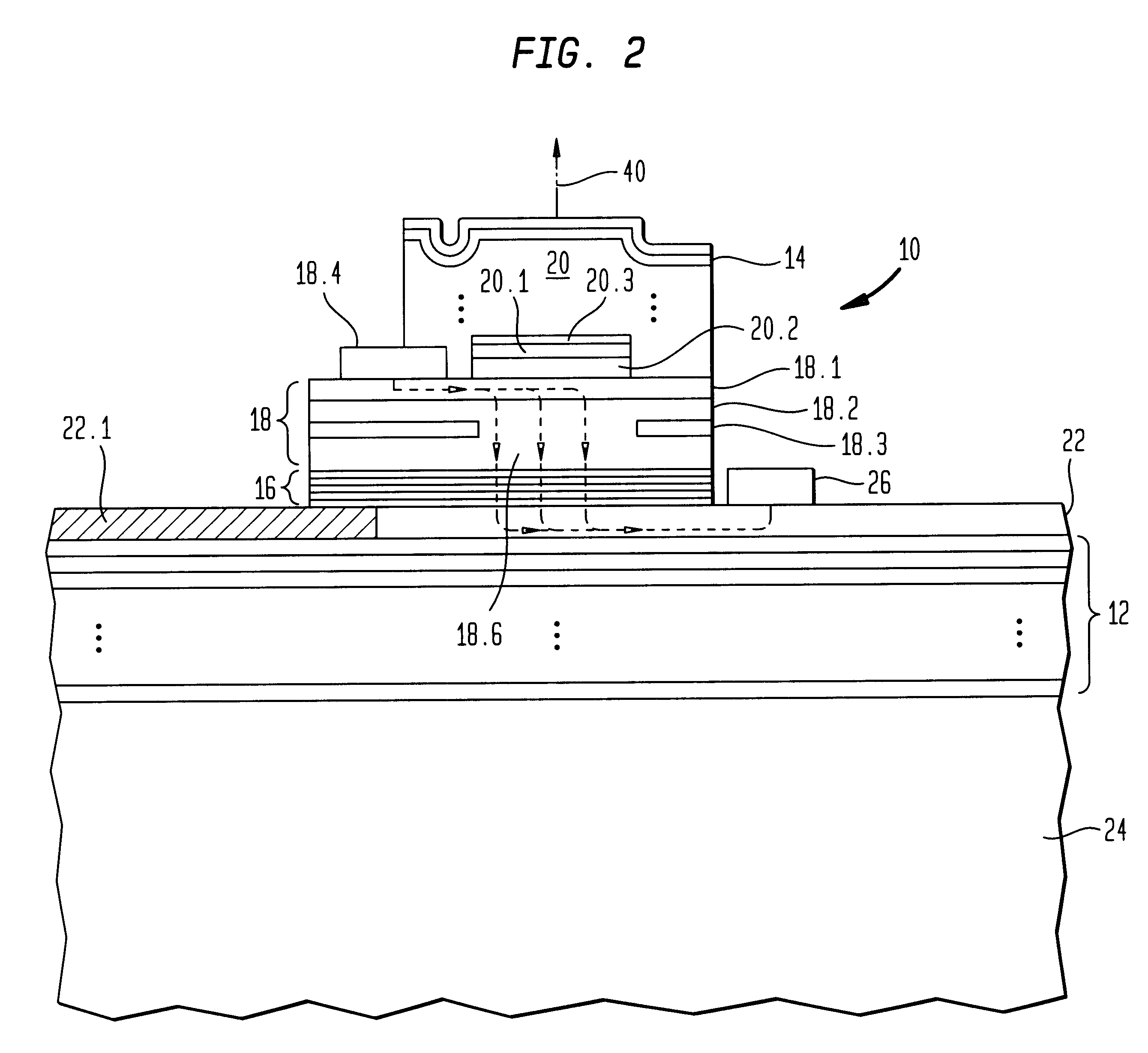
The following example describes the fabrication of a lateral injection VCSEL of the type depicted in FIGS. 2-3. Although the fabrication of a single device is described, it will be understood, of course, that typically an array of devices is formed on a single wafer. The various material, dimensions, and other parameters are provided by way of illustration only and, unless otherwise expressly indicated, are not intended to limit the scope of the invention. MOCVD was used to grow all of the semiconductor layers. P-type layers were doped with C, whereas n-type layers were doped with Si. The term undoped epitaxial layer as used herein generally means that the layer was not intentionally doped, but may have been subject to low level doping from background dopants in the growth chamber.

The VCSEL 10 was designed for operation for bottom emission at a free-space center wavelength of about 964 nm, a threshold current of about 1 mA, an operating current of about 3-5 mA, and a power dissipati...


PUM


Abstract

A lateral injection VCSEL comprises upper and lower mirrors forming a cavity resonator, an active region disposed in the resonator, high conductivity upper and lower contact layers located on opposite sides of the active region, upper and lower electrodes disposed on the upper and lower contact layers, respectively, and on laterally opposite sides of the upper mirror, and a current guide structure including an apertured high resistivity layer for constraining current to flow in a relatively narrow channel through the active region, characterized in that a portion of the lower contact layer that extends under the top electrode has relatively high resistivity. This feature of our invention serves two purposes. First, it suppresses current flow in parallel paths and, therefore, tends to make the current density distribution in the aperture more favorable for the fundamental mode. Second, it reduces parasitic capacitance.

Description

1. Field of the InventionThis invention relates generally to lateral injection vertical cavity surface-emitting lasers (VCSELs) and, more particularly, to such lasers that provide for both improved current distribution and reduced parasitic capacitance.2. Background of the InventionA conventional lateral injection VCSEL as depicted in FIG. 1 comprises an active region 60 disposed in a cavity resonator formed by a pair of multi-layered mirrors 52 and 54. A current confinement structure 58 constrains current to flow in a relatively narrow channel through the active region. The structure 58 includes a high resistivity layer 57 having an aperture 59 through which current flows from an annular upper contact 54 to an annular lower contact 56. More specifically, as shown by the dashed lines 40 and 42, current flows from upper contact 54 into high conductivity layer 46, continues essentially horizontally along layer 46, then flows vertically through aperture 59 to high conductivity current ...

Claims


Application Information

Patent Timeline
Patent Type & Authority Patents(United States)
IPC IPC(8): H01S5/183H01S5/00H01S5/042
CPCH01S5/18341H01S5/0421H01S5/0422H01S5/18308H01S5/18327H01S5/18369H01S5/18377H01S5/2063
Inventor CHIROVSKY, LEO MARIAD'ASARO, LUCIAN ARTHURHOBSON, WILLIAM SCOTTLOPATA, JOHN
Owner LUCENT TECH INC
Why Eureka
Try Eureka