Cooling fan in sync with audio output level

a cooling fan and audio output technology, applied in the direction of domestic cooling apparatus, electric apparatus casings/cabinets/drawers, instruments, etc., can solve the problems of fan noise that interferes with the playing of music, certain circuits requiring cooling however, and tends to operate in bursts, and can be quite annoying

Inactive Publication Date: 2002-12-17
KONINK PHILIPS ELECTRONICS NV
View PDF11 Cites 38 Cited by
  • Summary
  • Abstract
  • Description
  • Claims
  • Application Information

AI Technical Summary

Problems solved by technology

The problem with using a fan is that a fan is typically turned on and left on during operation of the electronic device causing fan noise to interfere with the playing of music or other audio or the general quiet of an environment in which the device is used.
Certain circuits requiring cooling however, tend to operate in bursts.
In fact depending on the audio output of the computer, the fan noise can be quite annoying, such as when trying to listen to a CD.

Method used


Image

  • Cooling fan in sync with audio output level
  • Cooling fan in sync with audio output level
  • Cooling fan in sync with audio output level

Examples


first embodiment

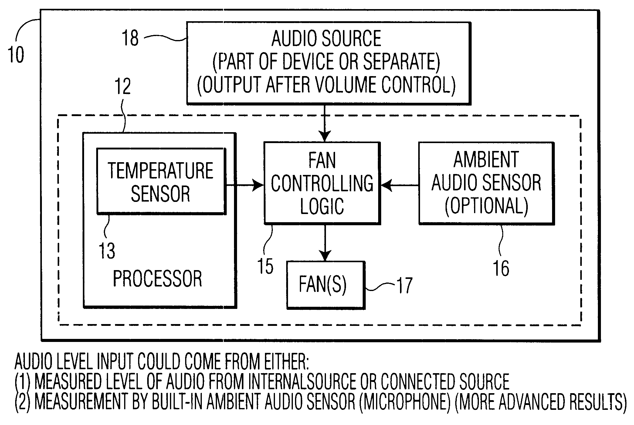
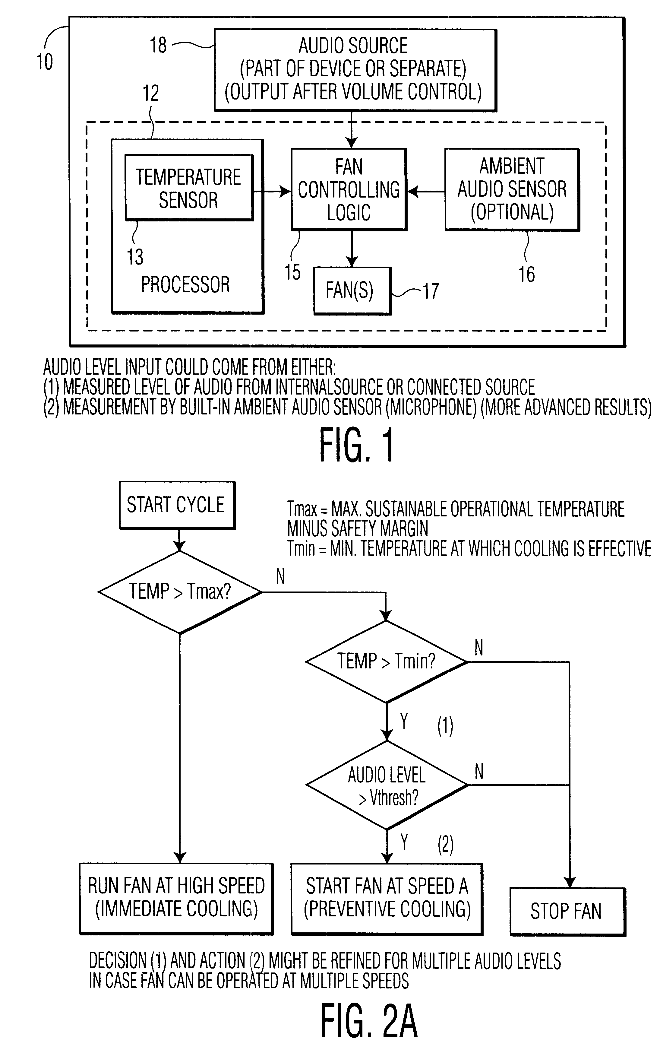
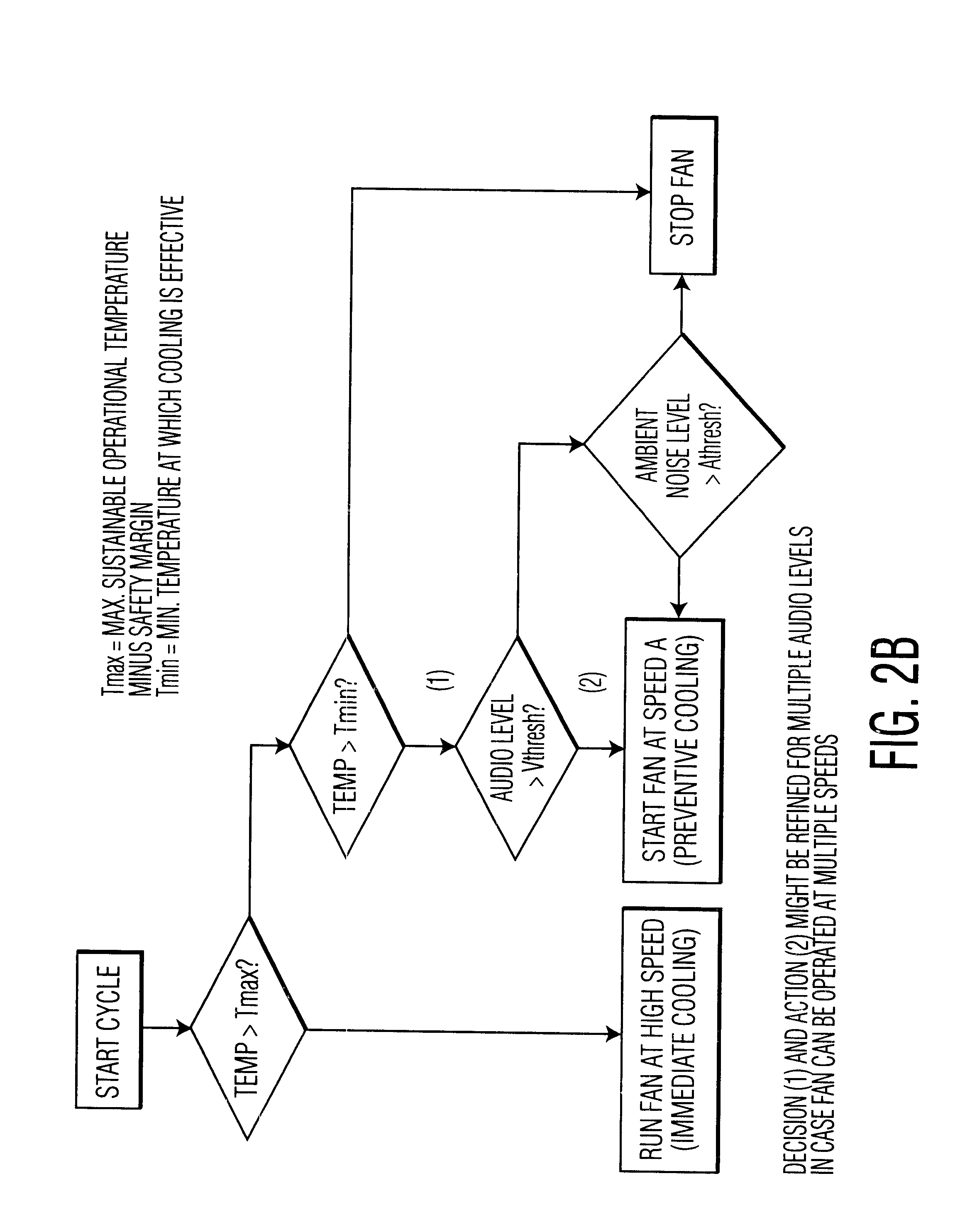
A temperature sensor is described in U.S. Pat. No. 5,870,614 incorporated herein by reference. FIG. 1 shows a block diagram in accordance with the invention. An electronic device such as a PC or home audio equipment 10 is provided with a processor 12, having a temperature sensor 13, fan controlling logic 15, a fan 17 and an audio source 18 (internal or external). The fan is controlled by logic circuitry 15 which receives inputs from the temperature sensor 13 and the audio source 18. Logic circuitry 15 can also be replaced by a microcontroller, microprocessor or other processor or software running such processor. FIG. 2A shows a flow chart of the operation of the embodiment in FIG. 1.

Temperature sensor 13 can be integrated in a semiconductor substrate or for example a processor 12 or located somewhere else within the electronic circuit. For ease of explanation it will be assumed that the temperature sensor 13 is located within the substrate. Temperature sensor 13 provides a signal in...

third embodiment

FIG. 3 shows a graph of the invention which also controls the fan speed. In this embodiment the fan speed is variably controlled based on the audio output level and the temperature of the semiconductor or device. (This graph also applies to the embodiment which controls the fan speed based on temperature and ambient noise level only.) In this case if the temperature of the semiconductor or device is at Tmin or less, the fan is always OFF. If the temperature of the semiconductor or device is less than Tmax then the audio source signal level is monitored. If the audio signal level is above Amax then the fan is on high speed and / or ambient noise level. If the temperature level is between Tmed and Tmax and the audio signal is less than Ahigh and greater than Vmed then the fan is run at medium speed. If the temperature level is less than Tmed and greater than Tmin and the audio output level is below Vmed then the fan is run on low speed. Obviously these levels can be partitioned for even...


PUM


Abstract

A method and device for controlling a cooling fan within an electronic device based on the temperature within the electronic device and the audio output level of the electronic device and / or the ambient noise level.

Description

The invention relates in general to cooling fans used in electronic devices and in particular to cooling fans which are controlled in part based on the audio output level of the electronic device and / or the ambient noise level.BRIEF DESCRIPTION OF THE PRIOR ARTThe power dissipated during operational use of an electronic circuit reveals itself as heat. The heat generated by an integrated circuit typically increases with increasing transistor density and with increasing clock frequency. The eventual temperature of a semiconductor substrate in a stationary state is determined by the balance between the heat generated and the heat carried off of the substrate. A conventional way to handle excessive heat is providing forced cooling using a fan.The problem with using a fan is that a fan is typically turned on and left on during operation of the electronic device causing fan noise to interfere with the playing of music or other audio or the general quiet of an environment in which the devi...

Claims


Application Information

Patent Timeline
Patent Type & Authority Patents(United States)
IPC IPC(8): G06F1/20H05K7/20
CPCG06F1/206H05K7/20209G01H11/06G11B33/142G11B33/144
Inventor BULTHUIS, WILLEM
Owner KONINK PHILIPS ELECTRONICS NV
Why Eureka
Try Eureka