Seals for hydraulic assemblies

a technology for sealing and hydraulic assemblies, applied in the direction of sealing, screwing, load-modifying fasteners, etc., can solve the problem of limited hydraulic chamber operative surface area

Inactive Publication Date: 2002-12-17
CURTISS WRIGHT FLOW CONTROL CORP
View PDF24 Cites 46 Cited by
  • Summary
  • Abstract
  • Description
  • Claims
  • Application Information

AI Technical Summary

Benefits of technology

The yield strength of the materials used is desirably in excess of the sum of pressure and radial loads induced by operation, for repeated operation. Otherwise the seal may be limited to a single use. Below the yield strength the rings will possess elastic properties, permitting re-use for a longer service life and durability.

Problems solved by technology

Often the available operative surface area of the hydraulic chamber is limited by the juxtaposition of adjoining features and the necessary thickness of its internal structure to withstand stresses generated by the introduced fluid pressure.

Method used


Image

  • Seals for hydraulic assemblies
  • Seals for hydraulic assemblies
  • Seals for hydraulic assemblies

Examples


Embodiment Construction

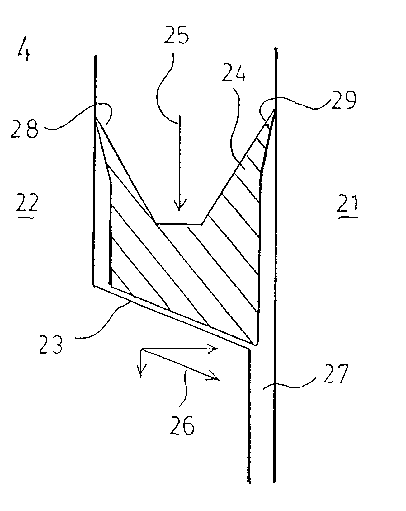
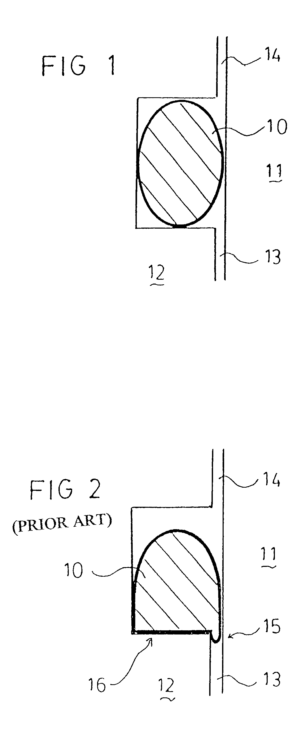
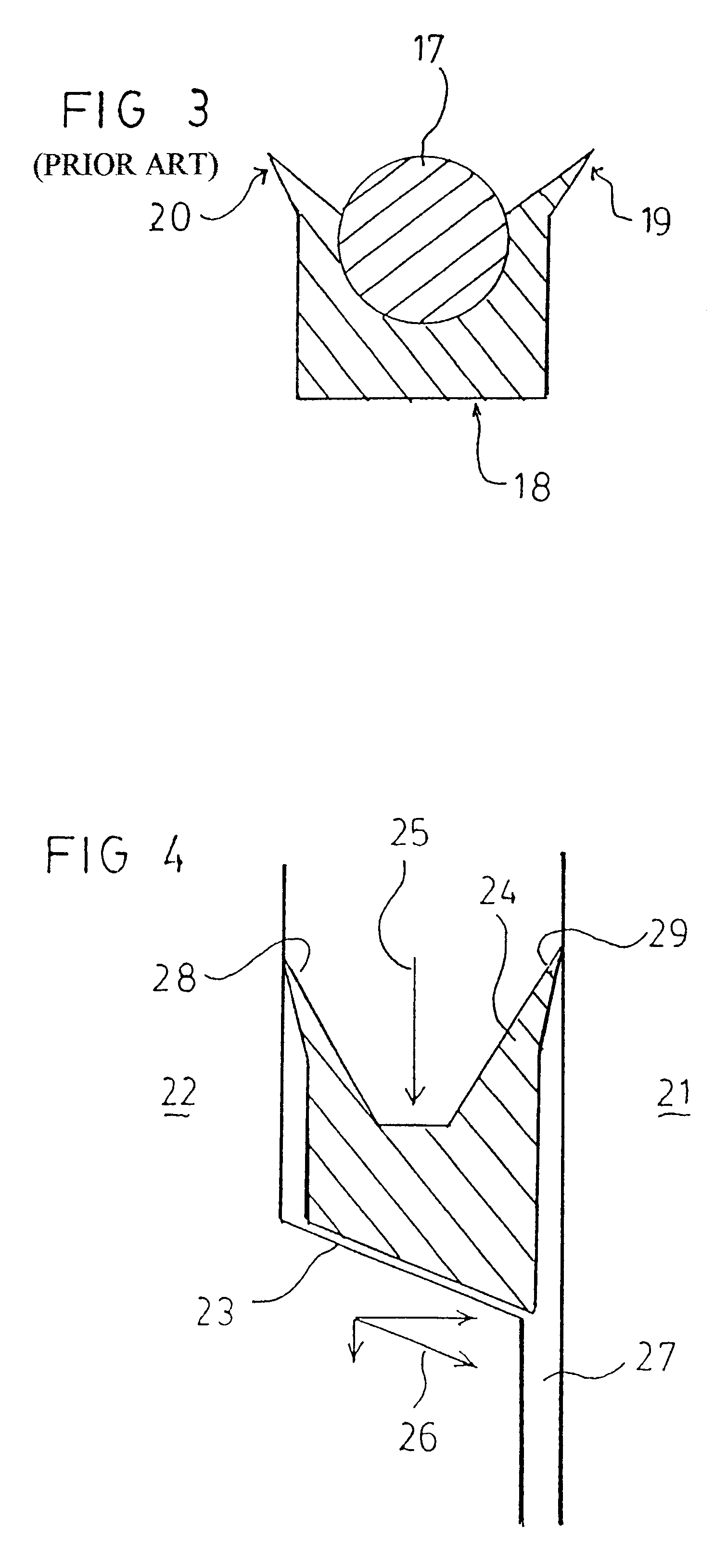
In FIG. 1 is seen a prior art interference type seal between two parts 11 and 12. The gap 13 is sealed against fluid under pressure in gap 14. This is referred to heroin as the Primary Sealing Mechanism.

The Primary Sealing Mechanism allows seal media to exert a light pressure against opposing surfaces to prevent passage of pressurizing fluid at low pressures yet allowing easy sliding contact between components. As the pressure increases, the force directed against the surface of the seal acts to deform the shape of the seal. This causes a transition of the actual point of contact at which sealing occurs from the low pressure point of contact to that area immediately adjacent the extrusion gap. At such time the seal material can be said to act simply as a barrier or plug to prevent loss of pressurizing fluid through the extrusion gap. This effect is herein described as the Secondary Sealing Mechanism.

FIG. 2 shows the shape ultimately adopted by the seal under increased pressure. The ...


PUM


Abstract

A seal for hydraulic assemblies operating at high temperatures having adaptations (19, 20, 49, 50) for low pressures sealing and configured to move across the gap to be sealed at higher pressures with an angled base on a slope (23, 44) or a cup shape (73, 74) nested into a groove (72). The seal at the point of the gap being an elastic, metallic material.

Description

THIS INVENTION relates to improvements in hydraulic mechanisms such as fasteners or nuts and in particular it relates to improvements in the seals to such mechanisms and fasteners.Hydraulic systems such as nuts and like type fasteners are known, The nuts provide a means by which a stud or bolt can be tensioned on being engaged by the nut, which nut is then hydraulically actuated to apply a tensile force in the stud or bolt. The nuts often operate under extremes of pressure and temperature.Hydraulic nuts or like type fasteners are typically pre-tensioned mechanically, after which a source of hydraulic pressure is applied to a chamber within the structure to generate an hydraulic force which applies an axial tensile force to a stud or nut engaged by the fastener. A locking collar may be used to retain that tension after release of the pressure from said chamber.The magnitude of the added tensile force is dependent upon the operative surface area of the hydraulic chamber in the nut and...

Claims


Application Information

Patent Timeline
Patent Type & Authority Patents(United States)
IPC IPC(8): F16J15/08F16B31/04F16L17/00F16B37/00F16B39/02F16J9/08F16J15/06
CPCF16J15/0887Y10S277/943
Inventor BUCKNELL, JOHN WENTWORTH
Owner CURTISS WRIGHT FLOW CONTROL CORP
Why Eureka
Try Eureka