Pneumatic conveyor for light-weight empty bottles

a pneumatic conveyor and bottle technology, applied in the direction of conveyors, loading/unloading, transportation and packaging, etc., can solve the problems of significant power loss, clogging of the conveyor guide path, and loss of the advantage of having a double guiding track

Inactive Publication Date: 2002-12-17
SALA JAIME MARTI
View PDF22 Cites 38 Cited by
  • Summary
  • Abstract
  • Description
  • Claims
  • Application Information

AI Technical Summary

Benefits of technology

This invention relates to a pneumatic conveyor for empty, lightweight bottles of the kind incorporating a support flange at an area of their neck and which are propelled by air jets along supporting and displacing guides.

Problems solved by technology

These conveyors which have a single pair of supporting tracks, show the drawback that the stability of the bottles run is very sensitive to any unbalance or irregularity between the thrust power of the air jets which impinge on the areas located above and the areas located under the flange guiding said bottles, so that the bottles have a significant likelihood to rotate each other and to get clogged in the conveyor guide path.
Therefore, the possible benefits arising from the advantage of having a double guiding track are lost because of the unbalance sustained by the areas of the bottles which receive the thrust of the air jets.
Actually, as the thrust is exclusively carried out by the part located above the guiding area, that is to say, above the flange, the bottles tend to tilt forwards, so that the front part of said flange presses against the sliding surface of the lower supporting track and the rear part against the upper guiding track, the friction force negatively increasing contrary to the bottles running forwards which implies a significant loss of power which means an increase of the air, supply cost and the likelihood of irregularity in the carriage and even eventual obstructions.
It is to be noted that in this kind of equipment the clogged bottles means a serious drawback because to remove them the line has to be stopped and part of the pressurizable chamber and of the guides must be dismounted which means an unbearable stop of the whole bottle feeding line at a bottling section, which obliges to arrange backup auxiliary conveying lines.
Actually, in this conveyor, as well as in the remaining conveyors considered, the pressurizable chamber or chambers feeding the blowing nozzles are made of a rigid material, generally metal sheet, which is expensive as a raw material, expensive to conform, namely if airtightness is required, because it implies cutting, folding and welding with some accurateness and that calls for bothersome mounting and dismounting and therefore, an also expensive general maintenance of the equipment.

Method used


Image

  • Pneumatic conveyor for light-weight empty bottles
  • Pneumatic conveyor for light-weight empty bottles
  • Pneumatic conveyor for light-weight empty bottles

Examples


Embodiment Construction

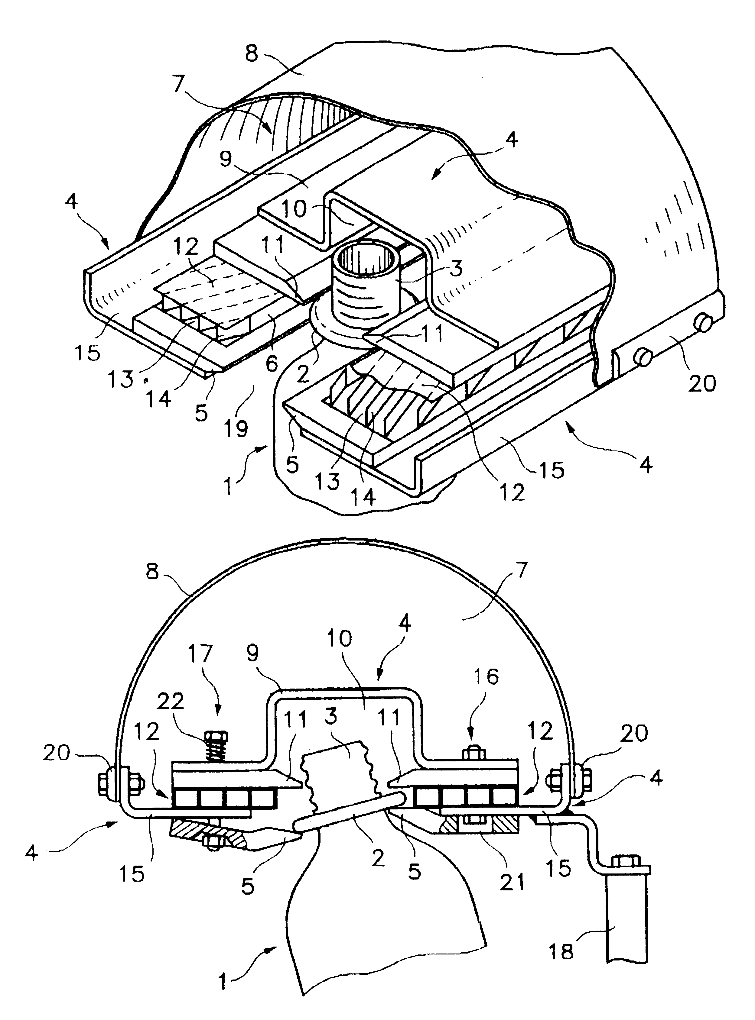
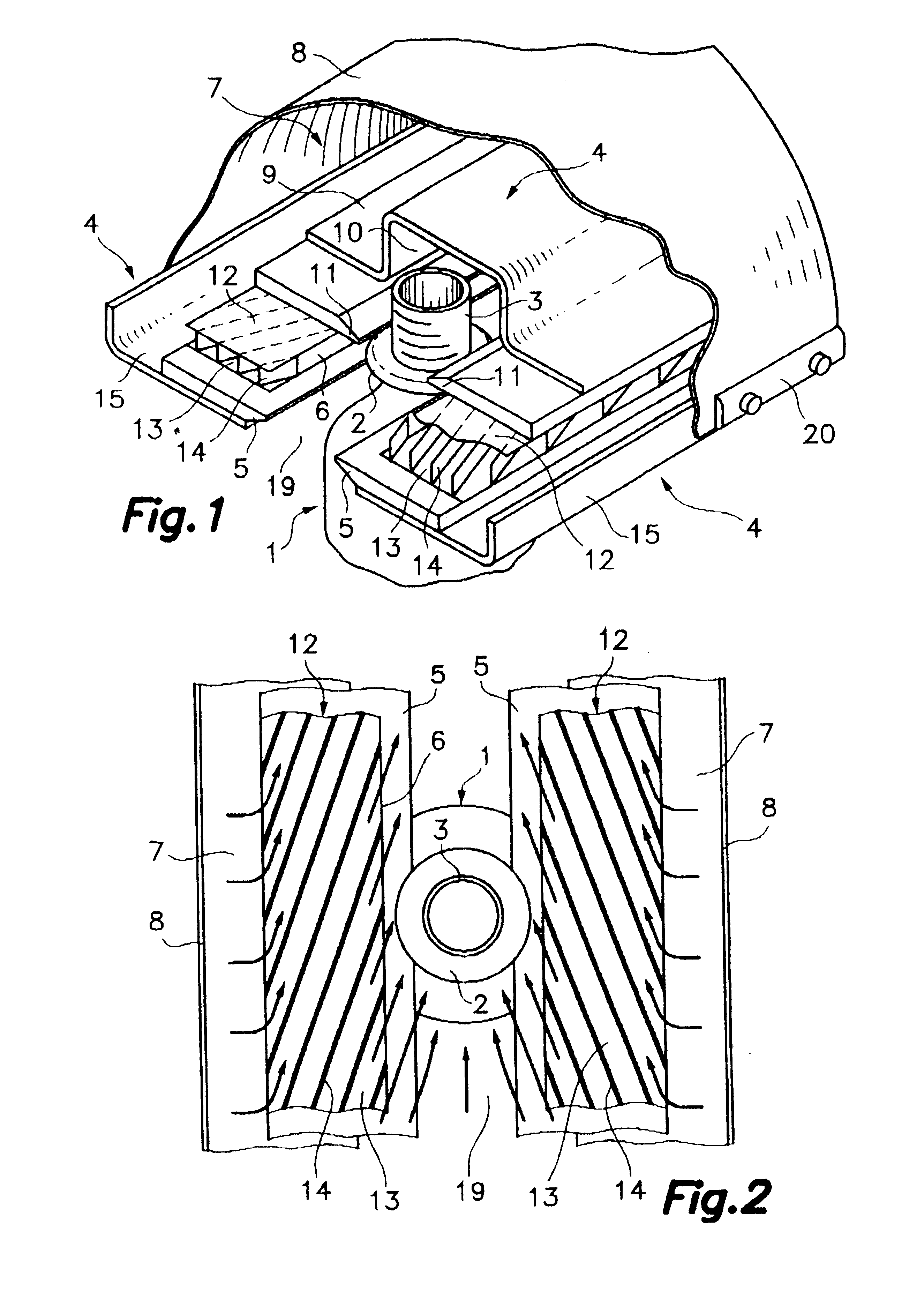
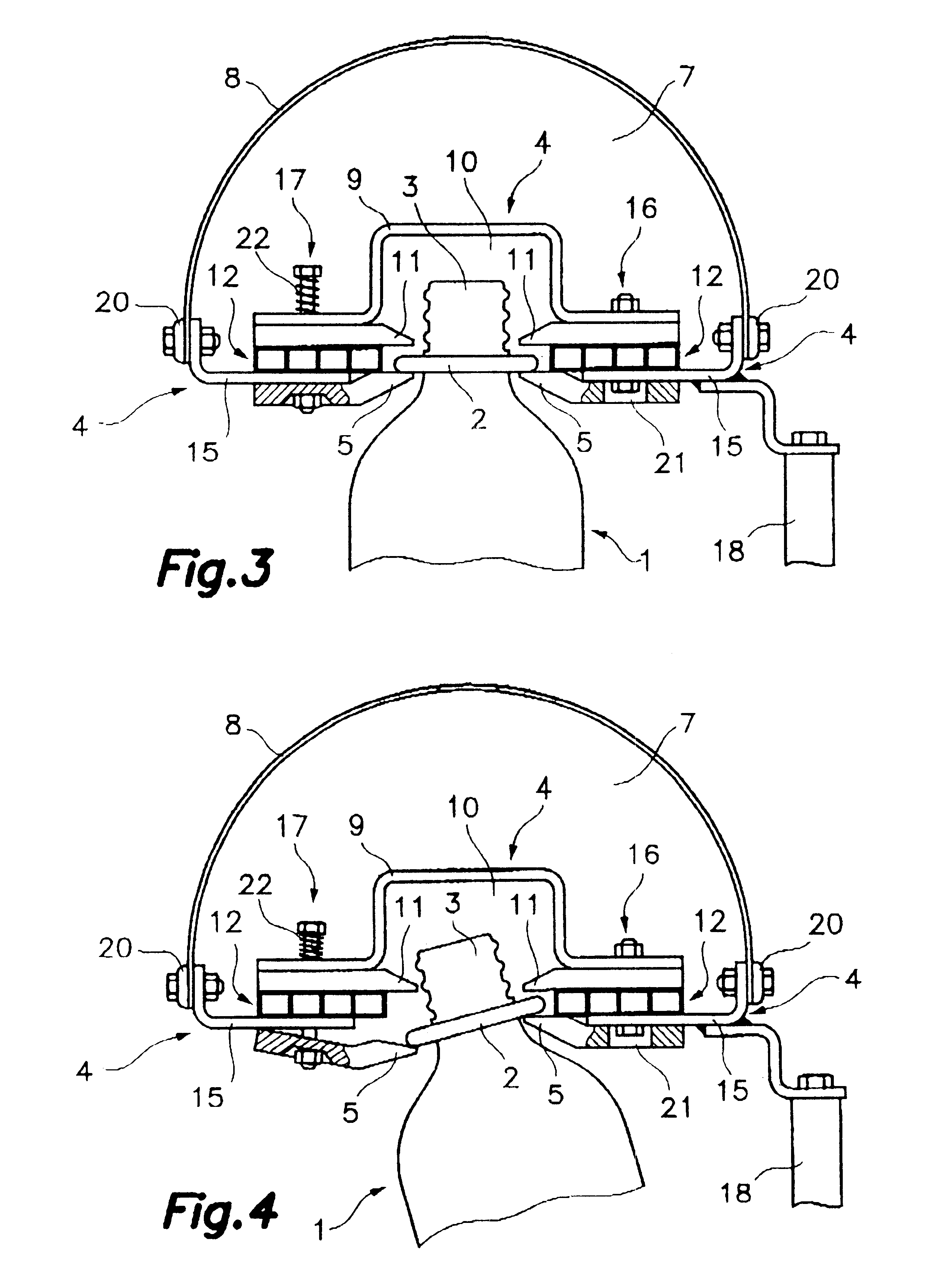
Referring first to FIG. 1 (see also FIGS. 3 and 4), numeral 1 designates a lightweight, empty bottle, typically in plastic material, incorporating a flange 2 at the area of its neck 3. The conveyor of the invention comprises a pair of parallel, coplanar supporting tracks 5, on each of which a body 12 is located which defines a plurality of outlet nozzles 6 along said track, and on each body 6 a second upper guiding track 11 is arranged. This way, the sandwiches formed by the tracks 5 and 11 with the body 12 interposed between them are arranged this way, said sandwiches 5, 11, 12 being separate by a gap sufficient for forming a guide path 19 for bottles 1, on which they are transferred, suspended, with the flanges 2 supported and sliding on the lower supporting tracks 5 and guided by the upper guiding tracks 11, under the thrust of compressed air jets ejected by the outlet nozzles 6 in a position favourable to the forwards run of the bottles 1 and which impinge just on the flange 2 a...


PUM


Abstract

Pneumatic conveyor for empty, lightweight bottles (1) of the kind incorporating a support flange (2) at an area of their neck (3). Said conveyor comprises a pair of coplanar, spaced apart supporting tracks (5) for supporting said flange (2), a pair of upper guiding tracks (11) opposed to tracks (5), and two bodies (12) arranged therebetween. Bodies (12) comprise passageways (13) communicating at one end with at least a pressurizable chamber (7) and defining at the other end blowing nozzles (6) which expel thrust air jets against the zone of the flange (2) of the bottles (1). The pressurizable chamber (7) is formed by a wrapping (8) easy to dismount, of a flexible and airtight material, such as a tarpaulin. The upper tracks (11) and bodies (12) are joined to the structure (4) by rigid means, while the tracks (5) are joined by elastic means allowing to manually withdraw the clogged bottles (1). Obturating plates serve for regulating the air flow through passageways (13).

Description

SCOPE OF THE INVENTIONThis invention relates to a pneumatic conveyor for empty, lightweight bottles of the kind incorporating a support flange at an area of their neck and which are propelled by air jets along supporting and displacing guides.STATE OF RELATED ARTIn the state of the art, different pneumatic conveyors of this kind are well-known, among which those disclosed in patents EP-0 070 931, EP-A-0 705 777, EP-A-0 790 200 and WO 90 / 10587. In each of them the conveyors disclosed show a general common configuration which comprises, at least, a supporting structure for, at least, two coplanar parallel tracks for supporting said flanges and apart from each other by a predetermined gap which defines a guide path of said bottles run; a plurality of blowing nozzles, distributed along each of said supporting tracks and located adjacent to them which provide air jets which propel the bottles; at least a pressurizable chamber communicated with said blowing nozzles; and at least an inlet ...

Claims


Application Information

Patent Timeline
Patent Type & Authority Patents(United States)
IPC IPC(8): B65G51/03B65G51/00
CPCB65G51/035
Inventor SALA, JAIME MARTI
Owner SALA JAIME MARTI
Why Eureka
Try Eureka