
Tie down building, system tie down, and method

a technology of tie-down and building, applied in the direction of rod connection, human health protection, shock proofing, etc., can solve the problems of manual manipulation and assembly is not self-adjusting, and achieve the effect of preventing the lifting of walls

Inactive Publication Date: 2002-12-17
ESPINOSA THOMAS M
View PDF36 Cites 59 Cited by
  • Summary
  • Abstract
  • Description
  • Claims
  • Application Information

AI Technical Summary

Benefits of technology

It is an object of this invention to provide a one way adjustment mechanism which will work under adverse conditions such as earthquakes, high winds and the like prevailing on building structures or other types of equipment including adjustment mechanisms in tooling, machinery, furniture and the like.
Yet another further object of this invention is to provide a fastener assembly which is inexpensive and readily manufactured and of simple assembly.

Problems solved by technology

The primary difficulties with these various developments has been the failure of the locking member to properly fit into the lock mode causing damage or shifting of the sleeve members relative to each other or which requires manual manipulation which can be difficult at times requiring additional tooling to get it released in order to provide adjustment.
When this fastener assembly either is serving directly as a product, or this fastener is combined with other components as a product, then after the installation thereof when a force is applied in one direction, this fastener assembly is self adjusting incrementally, as needed in travel or actuation; yet when a force is applied in the opposite direction, this fastener assembly is not self adjusting and there is no travel or actuation.

Method used


Image

  • Tie down building, system tie down, and method
  • Tie down building, system tie down, and method
  • Tie down building, system tie down, and method

Examples


embodiment 12

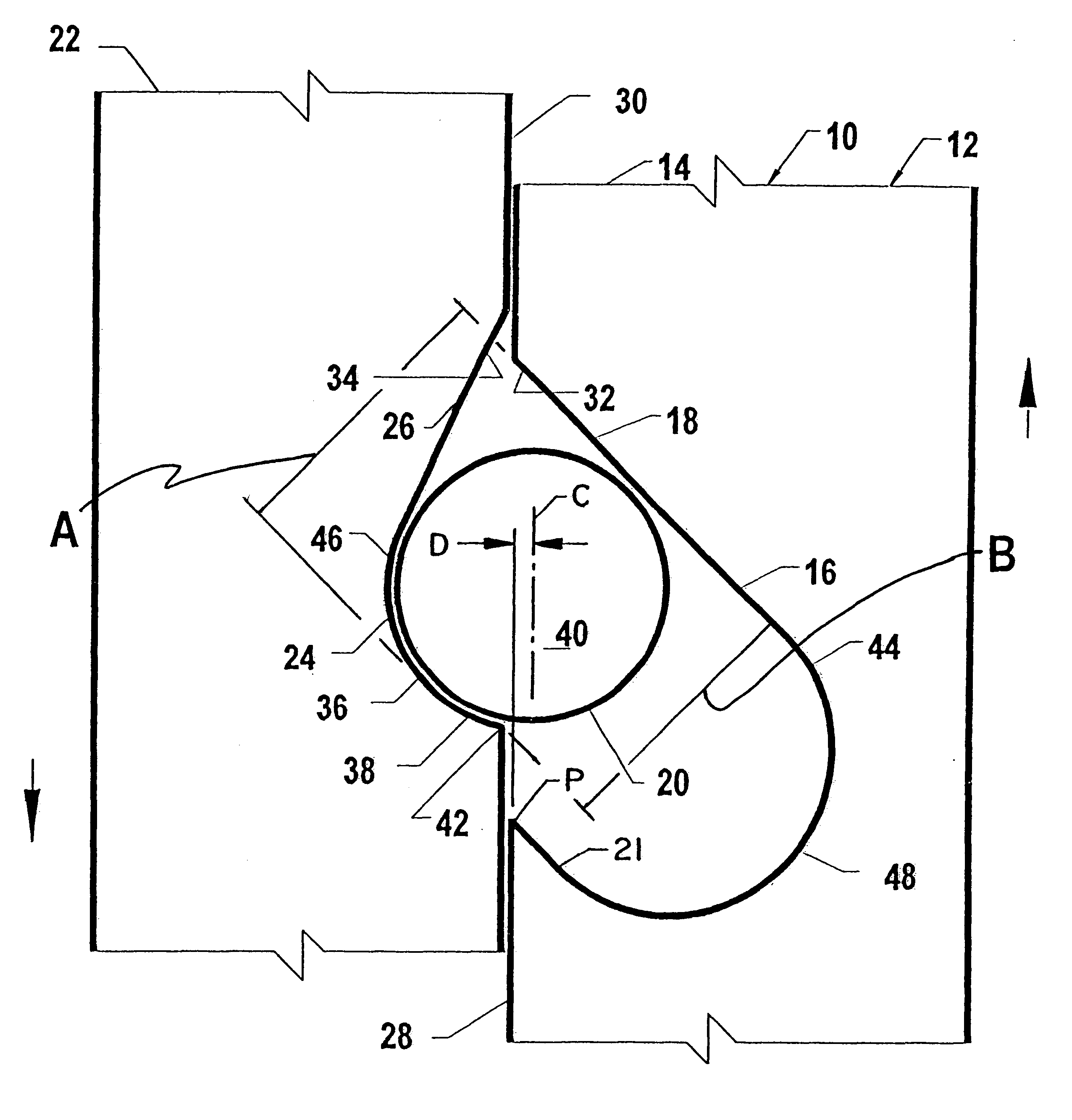
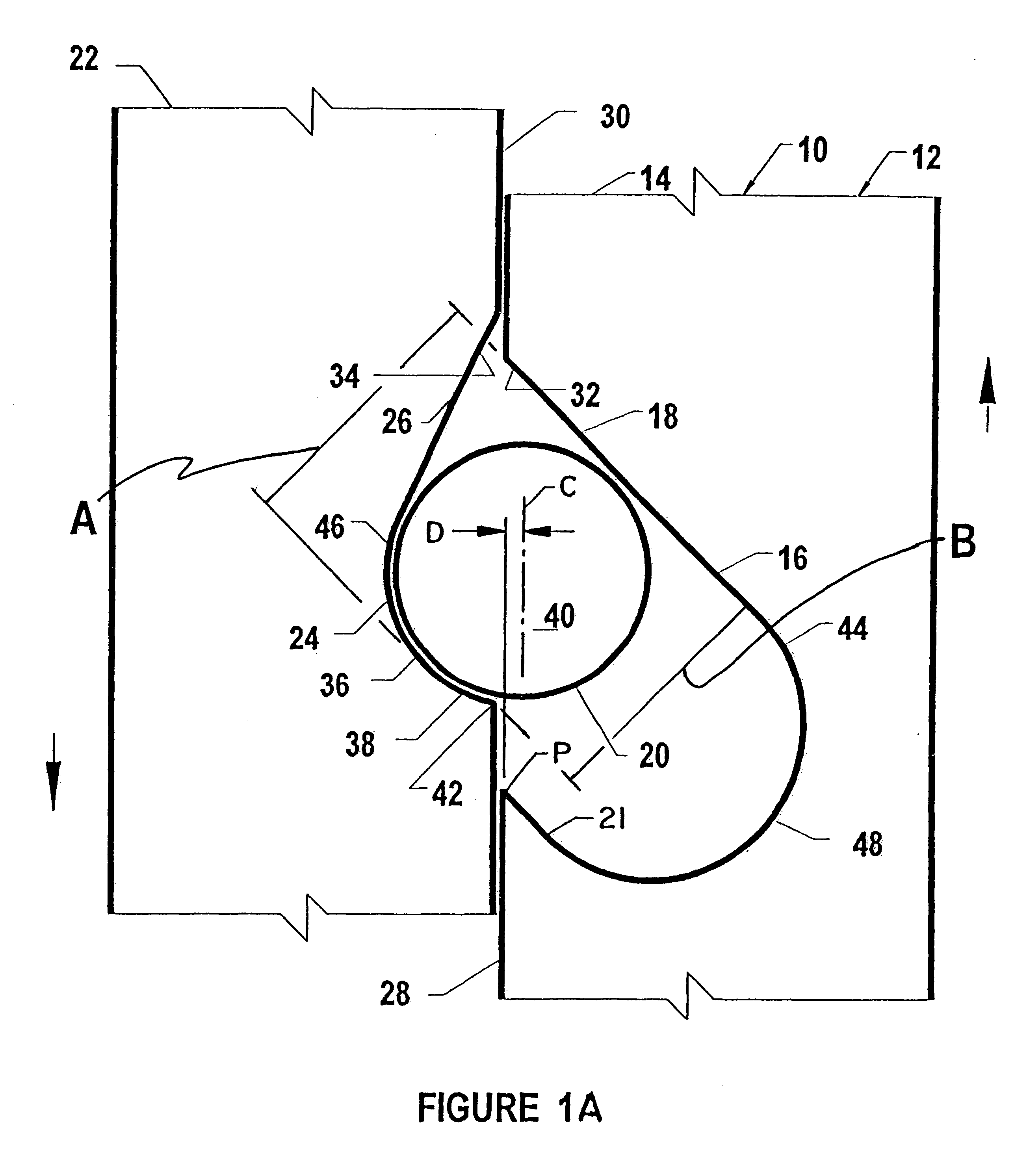
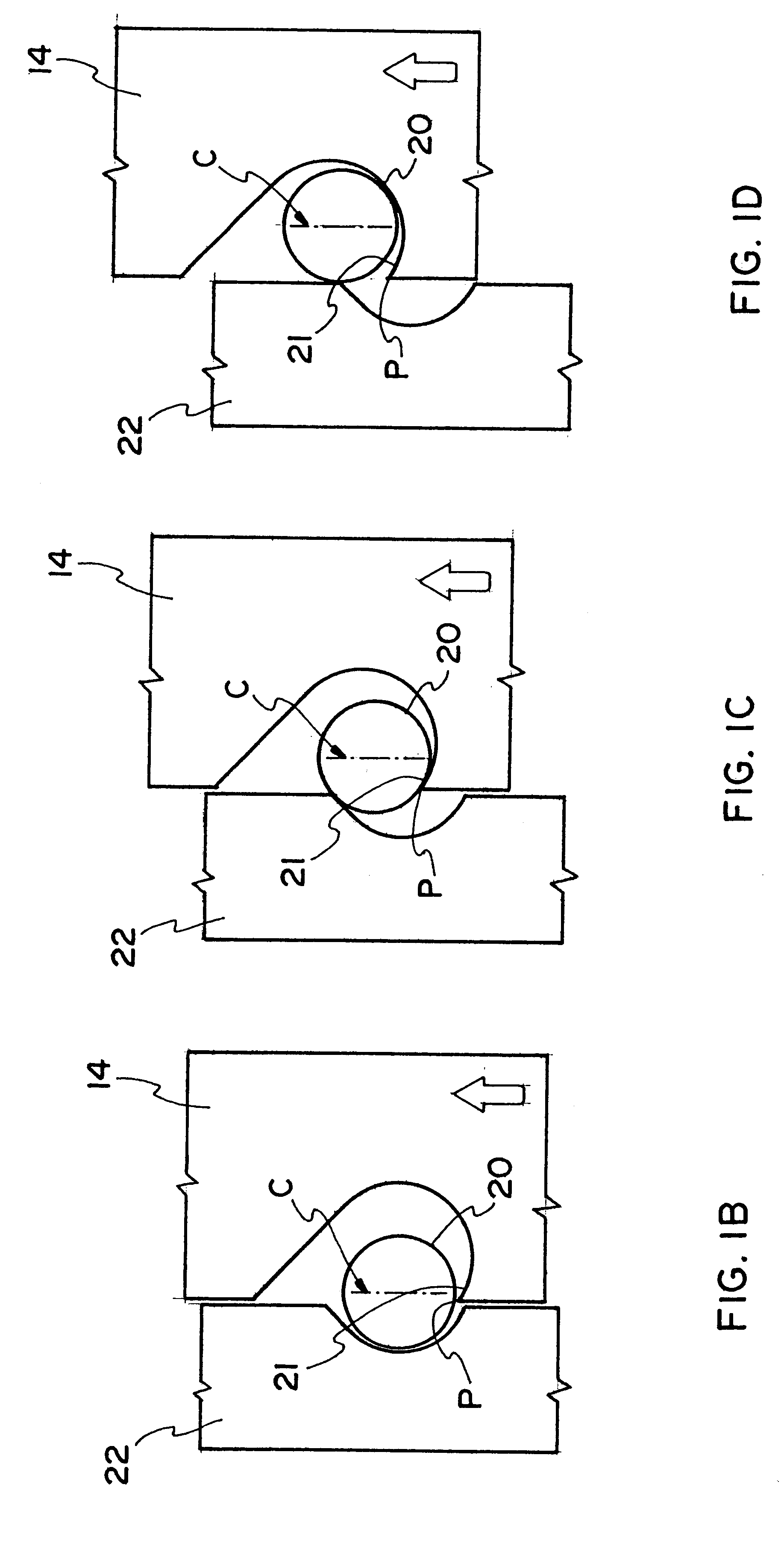
The fastener assembly 10, in the three member embodiment 12, is illustrated in FIGS. 1 through 8, to show a preferred arrangements of at least the minimal portions of at least three members, and how the respective relative movements thereof occur, during the sequences of their locking, in the presence of a relative force applied in one direction, and their incremental movement, in the presence of a relative force applied in the other direction. The assembly 10 may be color coded.

The first member 14 is oriented in some instance longitudinally axially and in others arcuately or circularly and, also called the receiver component 14, has a full receiving volume 16, with a cam surface 18, arranged on a bias, i.e., on an angle, so cam surface 18 is effective in guiding the movement of the third member 20 showing a center line C, also called the locking component, into and out of the full receiving volume 16. A third member 20 is circular-in-cross-section and may be a ball, ring or a rolle...

embodiment 244

As illustrated in FIG. 48, an embodiment 244 is provided, wherein the first member 246, having a smooth internal surface 248, and pre-fitted with locking components 234, received in full receiving volumes 232, along with other like sub assemblies 250, not shown, are placed about an extended member 252, having a circular cross section. At a selected location along the extended member 252,the sub assembly 250 is positioned on the extended member 252. Then the second member 254 having partial receiving volumes 240, and also having an axially directed opening 256, is moved to be positioned about the extended member 252. Thereafter, the second member 254 is moved axially for one way axial movement relative to the first member 246 to fully receive the first member 246. At this selected, location, another selected part, not shown, is often secured to the second member 254 during the fabrication or manufacture of an overall product or assembly, not shown.

THE COMMON FEATURES AND COMMON OBJEC...


PUM


Abstract

A fastener assembly 10, in respect to forces which are subsequently applied, after the installation thereof, when forces is applied in one direction, this fastener assembly 10 is self adjusting incrementally, as needed in travel or actuation; yet when a force is applied in the opposite direction, this fastener assembly 10 is not self adjusting and there is no travel or actuation. The invention includes also the building structure and method.

Description

BACKGROUND HISTORYIn the development of lock detent mechanisms which provide a movement in one direction and prevent movement in the opposite direction, Hendricks, U.S. Pat. No. 2,388,056, shows an adjustable stool or the like furniture article which can be moved in one direction and locked against movement in the other direction by means of a ball detent type construction. A release mechanism is provided. Aldridge also shows a detent lock mechanism of a general type in which there are a pair of sleeves with recesses on both sides for receiving a third member. The mechanism operates in one direction and locks in the opposite direction but can be released by a release spring.Shiga, U.S. Pat. No. 5,549,011, discloses a three member structure providing inner and outer members which are recessed and provide locking in one direction and adjustment in the other direction for the third member which can be, by centrifugal force moved into a "fish hook" like pocket, so that movement in one d...

Claims


Application Information

Patent Timeline
Patent Type & Authority Patents(United States)
IPC IPC(8): E04H9/14E04H9/02F16B21/16F16B21/18F16B21/00F16D41/066F16D41/00F16B7/00F16B7/10E04B1/00F16B7/16F16B37/00
CPCE04C5/08E04H9/02E04H9/14F16B7/105F16B21/16F16B37/00F16D41/064F16B21/18E04B2001/2688Y10T403/7086Y10S52/11Y10S411/916F16D2041/0646Y10T403/32434Y02A50/00E04H9/023
Inventor ESPINOSA, THOMAS M.
Owner ESPINOSA THOMAS M
Learn More