Valve timing control device of internal combustion engine

a timing control and internal combustion engine technology, applied in valve arrangements, machines/engines, mechanical equipment, etc., can solve the problems of bulky construction of the relative rotation angle control mechanism and the increase in the size of the helical gears

Inactive Publication Date: 2003-01-07
UNISIA JECS CORP
View PDF7 Cites 46 Cited by
  • Summary
  • Abstract
  • Description
  • Claims
  • Application Information

AI Technical Summary

Benefits of technology

That is, according to the present invention, there is provided a valve timing control device of an internal combustion engine, which is compact in size and assures a smoothed rotation angle change of the shaft member relative to the timing pulley without producing uncomfortable noises.
According to a first aspect of the present invention, there is provided a valve timing control device of an internal combustion engine, which comprises a drive rotation member rotated about a given axis by a crankshaft of the engine; a driven rotation member rotated about the given axis together with a camshaft of the engine; a relative rotation angle control mechanism through which the drive and driven rotation members are coaxially connected, the relative rotation angle control mechanism having a movable control member which, when actuated, varies a relative rotation angle between the drive and driven rotation members in accordance with an operation condition of the engine, the relative rotation angle control mechanism comprising a radial guide provided by one of the drive and driven rotation members; the movable control member guided by the radial guide in a manner to move in a radial direction with respect to the given axis; a link which links the movable control member to a given portion of the other of the drive and driven members, the given portion being positioned away from the given axis in a radial direction; an intermediate rotation member rotatable about the given axis relative to both the drive and driven rotation members; a spiral guide provided by the intermediate rotation member to guide the movement of the movable control member, so that rotation of the intermediate rotation member relative to the radial guide induces a radial movement of the movable control member; and a sliding resistance reducing structure arranged between the movable control member and the intermediate rotation member to reduce a sliding resistance produced when the movable control member is moved.

Problems solved by technology

However, due to the nature of the mutually meshed two helical gears, a considerable meshing resistance is inevitably produced by them, which tends to deteriorate a smoothed angle change of the shaft member relative to the timing pulley.
Furthermore, if, for reducing the meshing resistance, the inclination angle of the helical teeth of each gear is increased, the size of these helical gears would become increased, which brings about a bulky construction of the relative rotation angle control mechanism.

Method used


Image

  • Valve timing control device of internal combustion engine
  • Valve timing control device of internal combustion engine
  • Valve timing control device of internal combustion engine

Examples


first embodiment

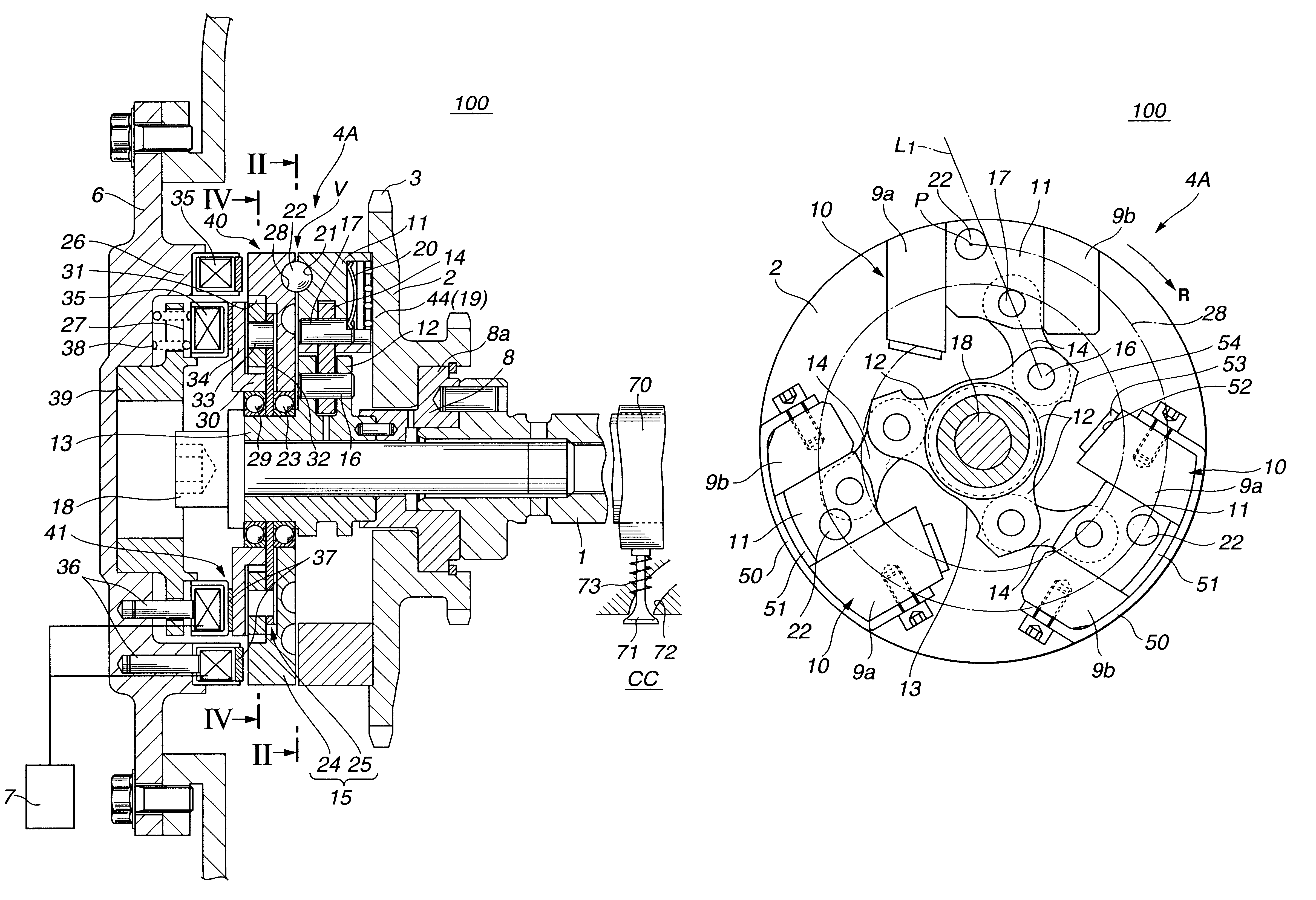
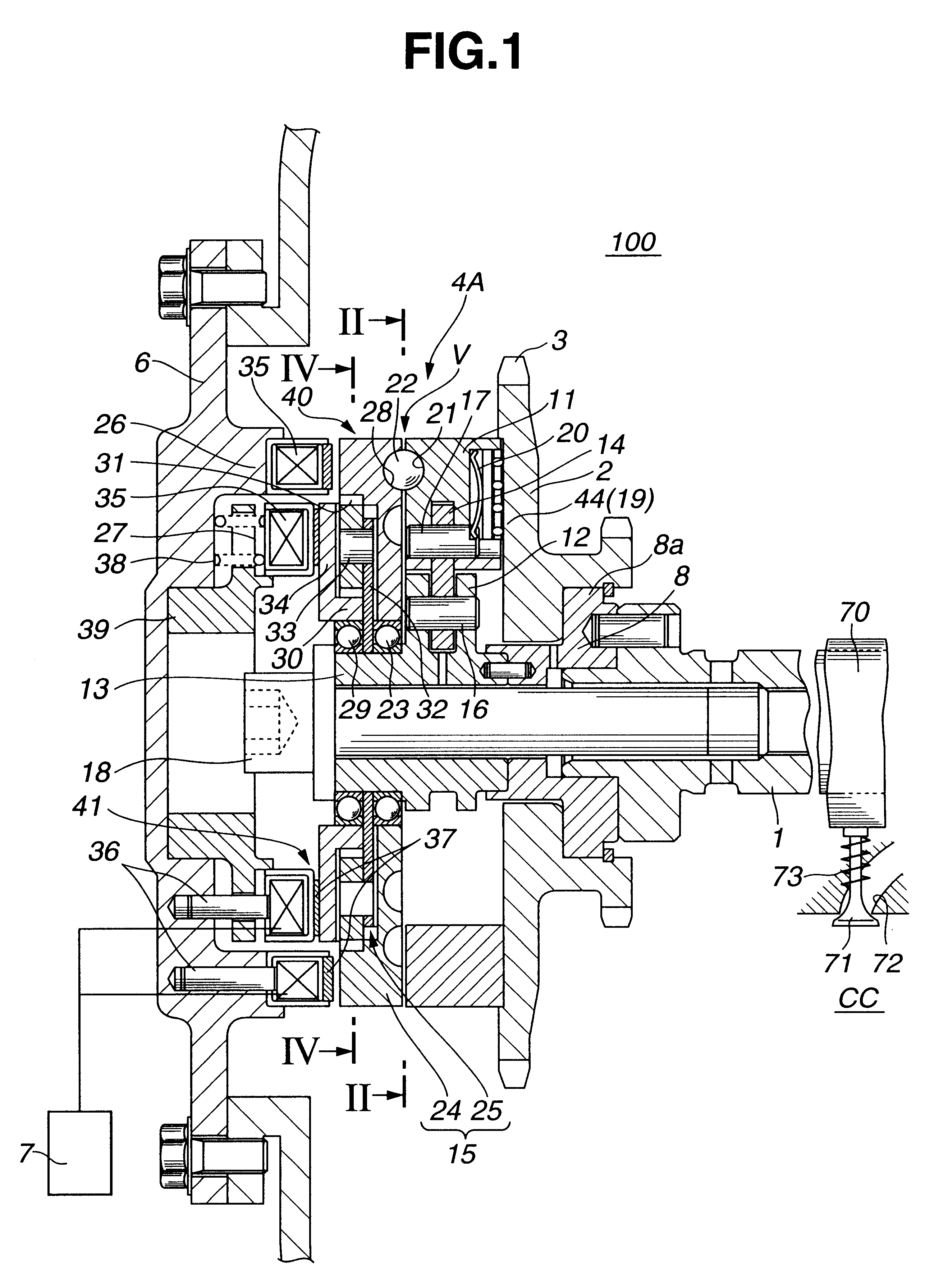
Referring to FIGS. 1 to 6 of the drawings, there is shown a valve timing control device 100 which is the present invention.

Although the valve timing control device 100 is described as being applied to intake valves of an internal combustion engine, the device 100 can be also applied to exhaust valves of the engine.

As is understood from FIG. 1, the valve timing control device 100 is arranged on a cylinder head which has a plurality of intake ports 72 (only one is shown) and a plurality of exhaust ports (not shown) which extend from combustion chambers "CC" in a known manner. Each intake port 72 has an intake valve 71 which functions to open and close the intake port 72. Due to function of a valve spring 73, each intake valve 71 is biased in a direction to close the intake port 72. The intake valves 71 are driven by respective cams 70 provided on a camshaft 1 which is supported on the cylinder head in a manner to rotate about its axis.

Rotatably disposed around a front (viz., left) end...

second embodiment

Referring to FIG. 7, there is shown but partially a relative rotation angle control mechanism 4B employed in a valve timing control device 200 of the present invention.

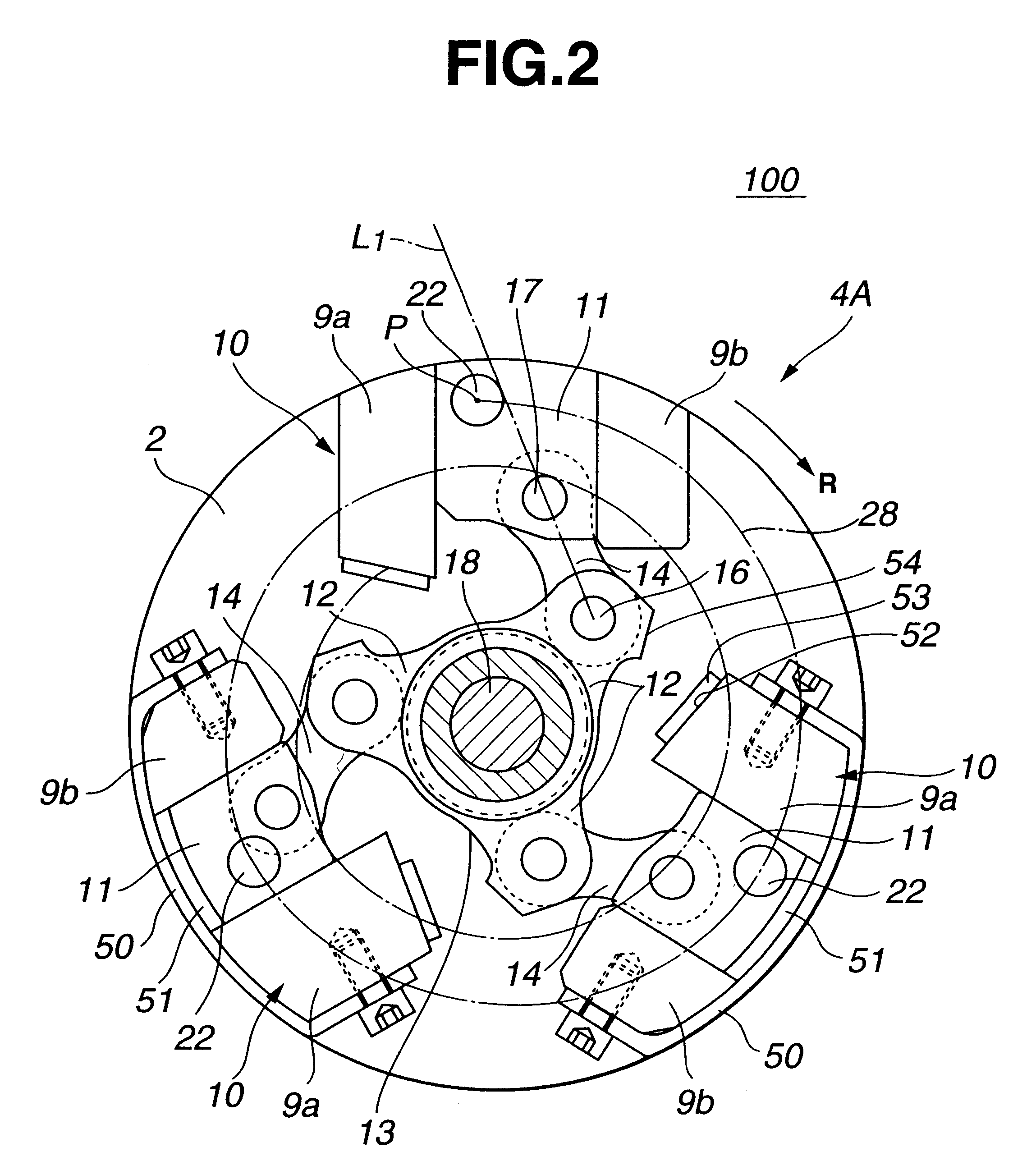
In this second embodiment 200, each sliding member 11 is formed on the front surface thereof with two semi-spherical recesses 21-1 and 21-2 into which two rolling balls 22 are respectively received, and these two recesses 21-1 and 21-2 are spaced in a radial direction with respect to the spiral guide groove 28 of the guide plate 24. Thus, the two rolling balls 22 are received in radially spaced portions of the spiral guide groove 28, as shown. Due to usage of the two rolling balls 22 for each sliding member 11, much smoother radial movement of the sliding member 11 is obtained. That is, due to usage of the two rolling balls 22, undesired inclination of the sliding member 11 is suppressed or at least minimized even when the line of action of the link arm 14 varies its inclination angle.

Referring to FIG. 8, there is sho...

third embodiment

Referring to FIG. 9, there is shown a partial sectional view of a relative rotation angle control mechanism 4C employed in a valve timing control device 300 of the present invention.

In this embodiment 300, each sliding member 11 is equipped with a biasing means for biasing the rolling ball 22 toward the guide plate 24. That is, the biasing means comprises a cylindrical bore 47 which is formed in the front part of the sliding member 11, a circular ball holder 46 which is slidably received in the cylindrical bore 47 and formed with a semi-spherical recess 21 for rotatably receiving the rolling ball 22, and a coil spring 48 which is received in the cylindrical bore 47 to bias the circular ball holder 46 toward the guide plate 24. Due to function of the biasing means having the above-mentioned construction, the rolling ball 22 is held much softly by the sliding member 11 as compared with the first and second embodiments 100 and 200, which promotes the smoothed traveling of the rolling b...


PUM


Abstract

A relative rotation angle control mechanism of a valve timing control device comprises a radial guide provided by one of drive and driven rotation members which are rotatable about a given axis. A movable control member is guided by the radial guide in a manner to move in a radial direction with respect to the given axis. A link links the movable control member to a given portion of the other of the drive and driven members. The given portion is positioned away from the given axis in a radial direction. An intermediate rotation member is rotatable about the given axis relative to both the drive and driven rotation members. A spiral guide is provided by the intermediate rotation member to guide the movement of the movable control member, so that rotation of the intermediate rotation member relative to the radial guide induces a radial movement of the movable control member. A sliding resistance reducing structure is further arranged between the movable control member and the intermediate rotation member to reduce a sliding resistance produced when the movable control member is moved.

Description

1. Field of the InventionThe present invention relates in general to a control device for controlling operation of an internal combustion engine, and more particularly to a valve timing control device which controls or varies an open / close timing of intake and / or exhaust valves of the internal combustion engine in accordance with an operation condition of the engine.2. Description of the Related ArtIn order to clarify the task of the present invention, one valve timing control device of an internal combustion engine will be briefly described, which is shown in Laid-open Japanese Patent Application (Tokkai-hei) 10-153104.In the valve timing control device of the publication, a timing pulley driven by a crankshaft of the engine is rotatably disposed around a shaft member which is integrally connected to a camshaft. A so-called "relative rotation angle control mechanism" is arranged between the timing pulley and the shaft member. The relative rotation angle control mechanism comprises ...

Claims


Application Information

Patent Timeline
Patent Type & Authority Patents(United States)
IPC IPC(8): F01L1/344F01L1/352F01L1/34
CPCF01L1/352F01L1/34
Inventor TODO, TAMOTSUWATANABE, MASAHIKO
Owner UNISIA JECS CORP
Why Eureka
Try Eureka