

Vehicle seat comprising a height-adjusting mechanism, and a control device for such a seat
a technology of height adjustment mechanism and control device, which is applied in the direction of seating furniture, operating chairs, domestic objects, etc., can solve the problems reducing the risk of serious injury to the seat occupant, etc., and limiting the weight and cost of the height adjustment mechanism. , to achieve the effect of reducing the mechanical strength of the assembly
- Summary
- Abstract
- Description
- Claims
- Application Information
AI Technical Summary
Benefits of technology
Problems solved by technology
Method used
Image

Examples
Embodiment Construction
In the different drawings, the same reference numbers refer to identical or similar elements.
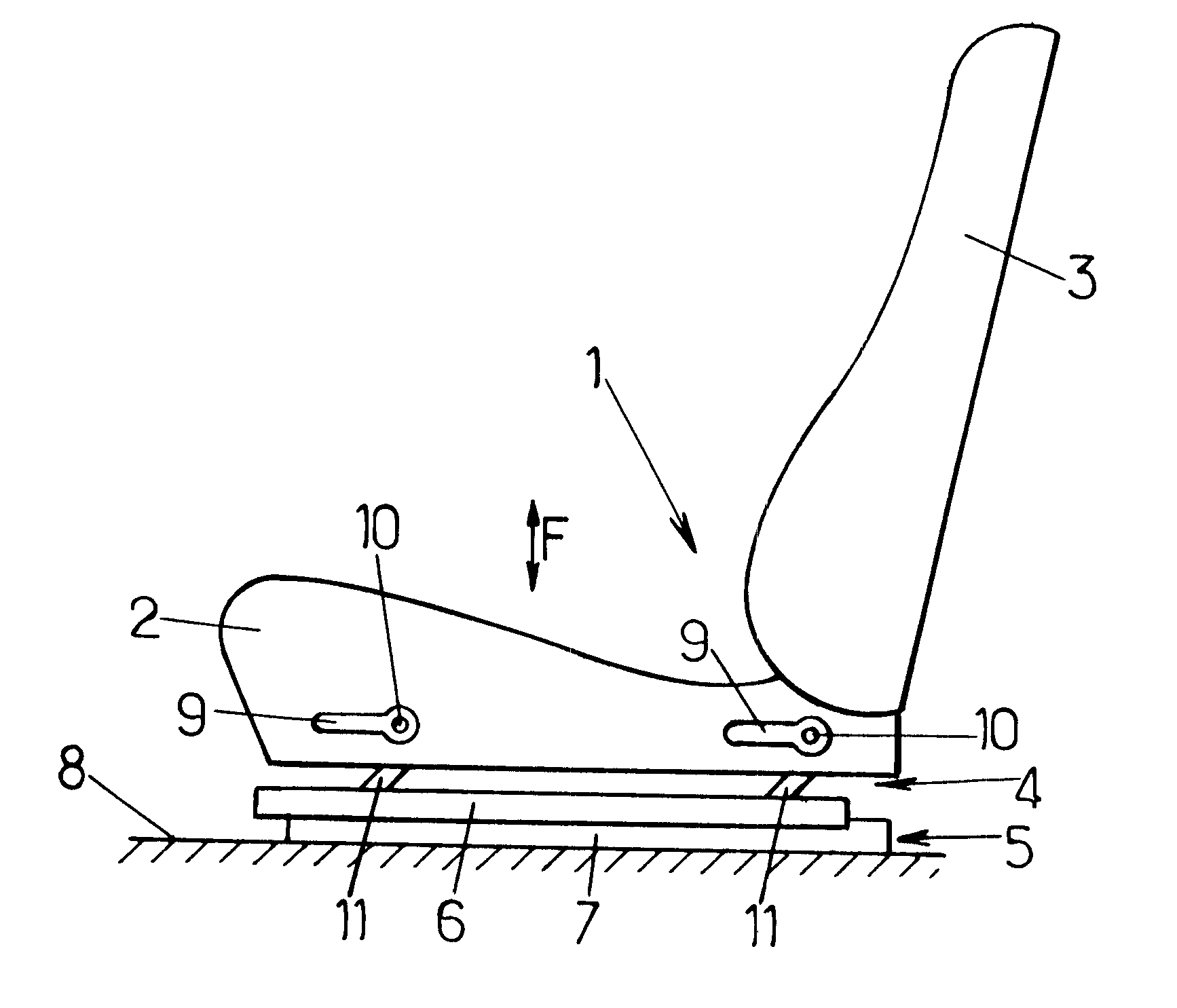
FIG. 1 shows a seat 1 of a motor vehicle comprising a cushion (seat part) 2 supporting a backrest 3 and itself supported by a height-adjusting mechanism 4 according to the present invention.
The height-adjusting mechanism 4 is mounted on the moving profile sections 6 of two longitudinal slides 5, only one of which is visible in FIG. 1, the two fixed profile sections 7 being integrally connected to the floor 8 of the vehicle.
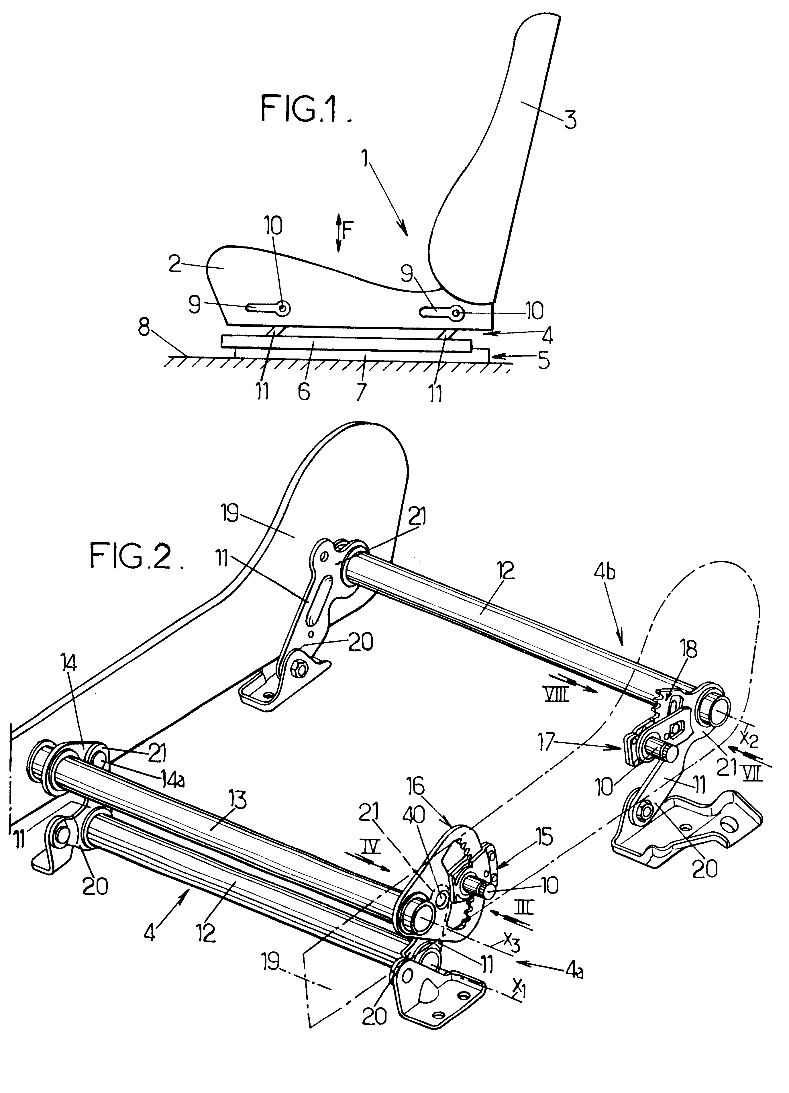
The height-adjusting mechanism 4 comprises two hand levers 9 (one front lever and one rear lever) each of which is movable around a transverse horizontal axis 10 and controls the pivoting of metal links 11, the lower ends 20 of which are mounted pivotally to moving profile section 6 of the corresponding slide and the upper ends 21 of which are connected directly or otherwise to rigid plates 19 at the sides of the cushion, as shown in FIG. 2.
The links 11 are generally four ...
PUM
 Abstract
Description
Claims
Application Information