Hydrogen powered aircraft

a hydrogen-powered aircraft technology, applied in the field of aircraft and their component systems, can solve the problems of heavy, drag-producing countermeasures for compensation, and high cost of a big increase in negative pitching moment, and achieve the effects of low power consumption, simplicity and reliability

Inactive Publication Date: 2007-10-16
AEROVIRONMENT INC
View PDF41 Cites 27 Cited by
  • Summary
  • Abstract
  • Description
  • Claims
  • Application Information

AI Technical Summary

Benefits of technology

[0019]The present invention provides aircraft, aircraft components and aircraft subsystems, as well as related methods. Various embodiments of the invention can provide flight over a wide range of speed

Problems solved by technology

While flaps might help increase the CL more than slats, they do so at the cost of a big increase in neg

Method used


Image

  • Hydrogen powered aircraft
  • Hydrogen powered aircraft
  • Hydrogen powered aircraft

Examples


Embodiment Construction

First Preferred Aircraft Embodiment

Fuel and Power Systems

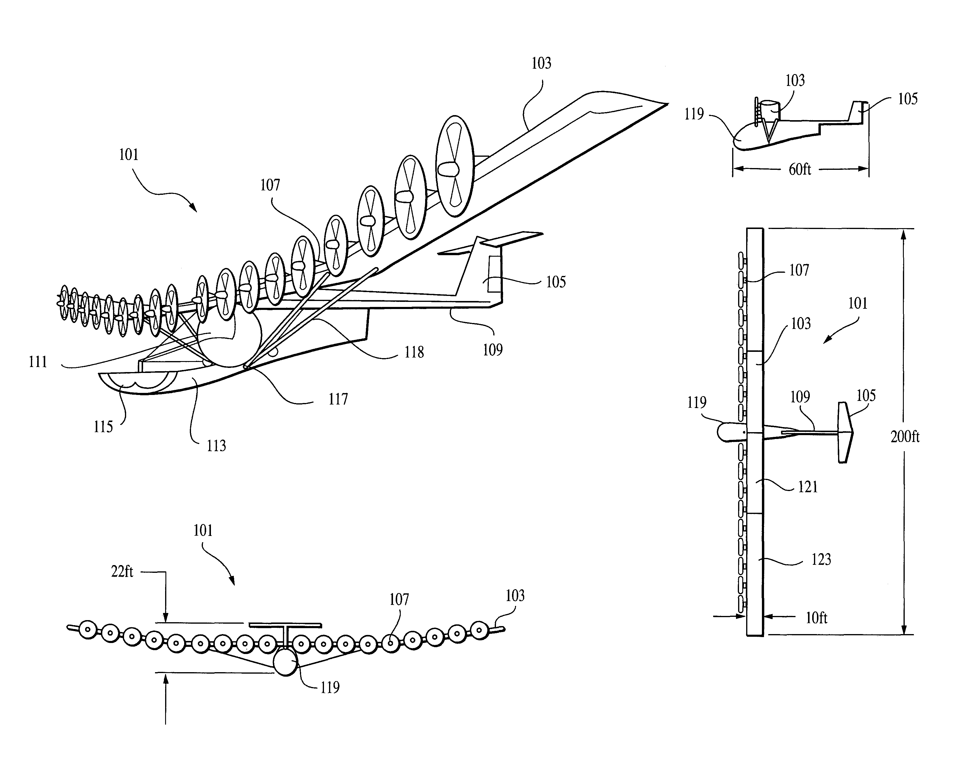
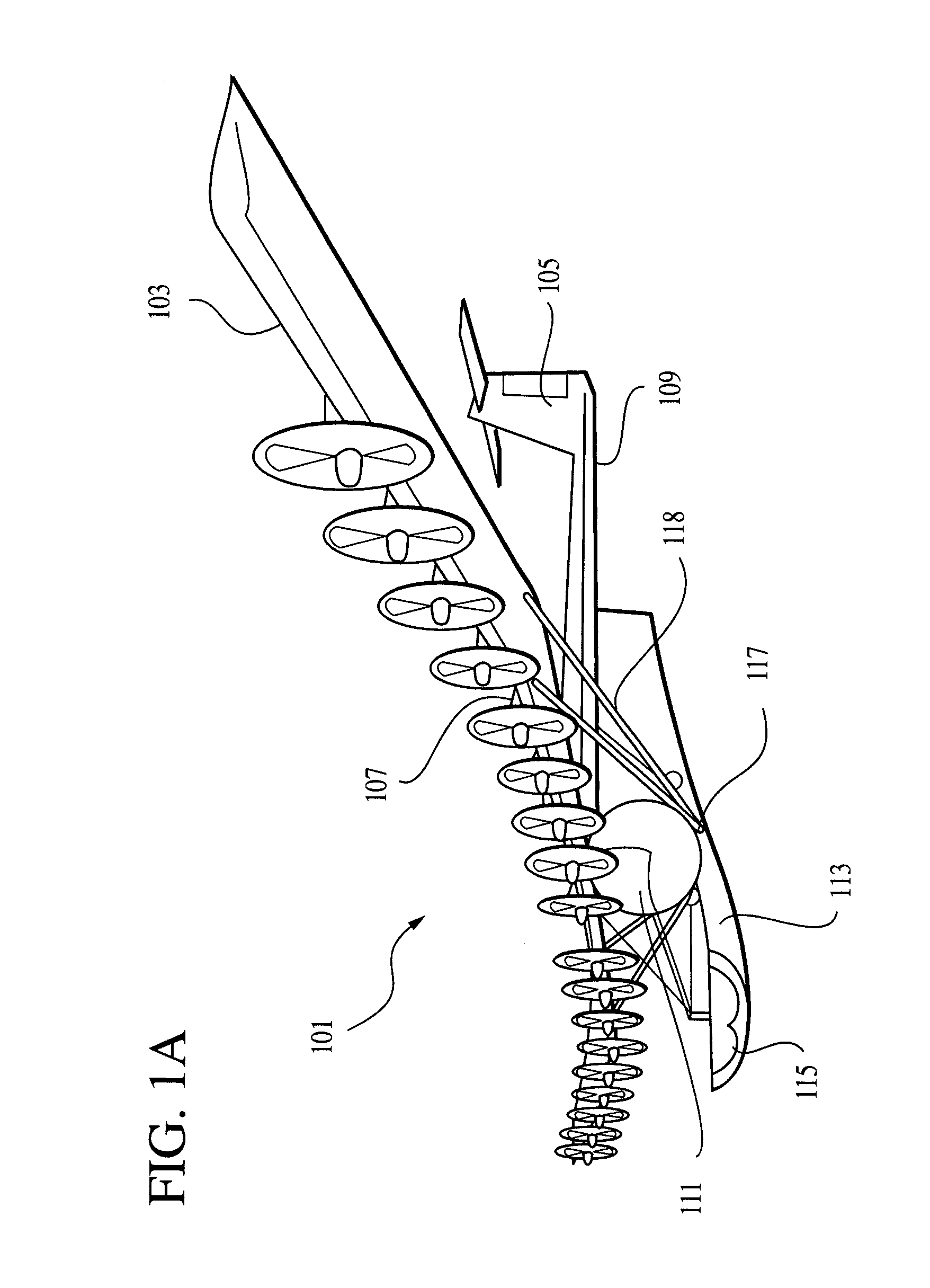
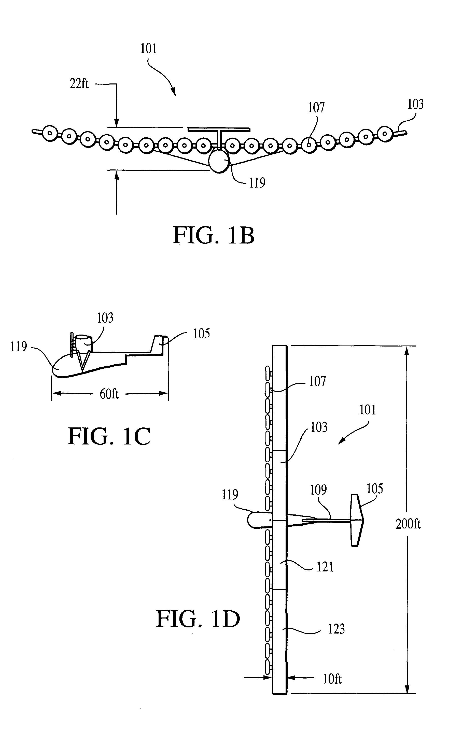
[0046]A first preferred, high-performance aircraft embodiment 101, capable of high-altitude stationkeeping within tight altitude and perimeter boundaries for extended periods of time, according to the present invention, is shown in FIGS. 1-4. The aircraft includes a wing 103, an empennage 105 and a plurality of motors 107. The empennage is preferably suspended from the wing on an extension 109 to provide the moment arm necessary to control pitch and yaw. Thus, the extension's length will be based on the empennage's surface area and the needed pitching and yawing moments.

[0047]A fuel tank 111 is suspended below the wing using trusses and / or wires. A payload section 113 containing a communications payload 115 extends forward from a lower portion 117 of the fuel tank, and is suspended using trusses, wires and / or supports 118. Preferably, the aircraft includes a cowling or fuselage portion 119 (not shown in FIG. 1 to expose conten...


PUM


Abstract

Disclosed is an aircraft, configured to have a wide range of flight speeds, consuming low levels of power for an extended period of time, while supporting a communications platform with an unobstructed downward-looking view. The aircraft includes an extendable slat at the leading edge of the wing, and a reflexed trailing edge. The aircraft comprises a flying wing extending laterally between two ends and a center point. The wing is swept and has a relatively constant chord. The aircraft also includes a power module configured to provide power via a fuel cell. The fuel cell stores liquid hydrogen as fuel, but uses gaseous hydrogen in the fuel cell. A fuel tank heater is used to control the boil-rate of the fuel in the fuel tank. The fuel cell compresses ambient air for an oxidizer, and operates with the fuel and oxidizer at pressures below one atmosphere. The aircraft of the invention includes a support structure including a plurality of supports, where the supports form a tetrahedron that affixes to the wing.

Description

BACKGROUND OF THE INVENTION[0001]The present application is a continuation-in-part of application Ser. No. 10 / 073,828, filed Feb. 11, 2002 now abandoned, is a divisional of application Ser. No. 09 / 826,424 filed Apr. 3, 2001 now U.S. Pat. No. 6,550,717, which claims priority from two U.S. provisional patent applications, Ser. No. 60 / 194,137, filed Apr. 3, 2000, and Ser. No. 60 / 241,713 now U.S. Pat. No. 6,550,717, filed Oct. 18, 2000, all four of which are incorporated herein by reference for all purposes.[0002]This invention relates generally to aircraft and their component systems, and, more particularly, to improved high-performance aircraft systems capable of high-altitude station keeping within tight altitude and perimeter boundaries for extended periods of time.[0003]A worldwide expansion in the demand for communication bandwidth is driving up the bandwidth requirements between satellites and ground-stations. One way to increase this satellite-to-ground bandwidth is to interpose...

Claims


Application Information

Patent Timeline
IPC IPC(8): B64D27/00B64C1/26B64C3/10B64C3/14B64C9/24B64C39/02B64C39/10B64D27/02B64D27/24B64D37/30
CPCB64C1/26B64C3/14B64C9/24B64C39/024B64C39/10B64D27/02B64D27/24B64D37/30B64C3/10B64C2201/187B64C2201/028B64C2201/042B64C2201/086B64C2201/104B64C2201/122B64C2201/141B64C2201/146B64C2201/165B64D2041/005Y02T50/12Y02T50/32Y02T50/44Y02T50/64Y02T90/36Y02T50/10Y02T50/30Y02T50/60Y02T50/40Y02T90/40B64U10/25B64U70/60B64U30/10B64U2101/20B64U2201/10B64U50/19B64U50/13B64U2201/20
Inventor MACCREADY, PAUL B.HIBBS, BART D.CURTIN, ROBERT F.
Owner AEROVIRONMENT INC
Why Eureka
Try Eureka