Electrical network of an aircraft

a technology of electric network and aircraft, applied in the direction of electric devices, emergency power supply arrangements, transportation and packaging, etc., can solve the problems of significant weight, development/maintenance cost of dedicated converters for each system, complex structure of electrical network,

Active Publication Date: 2016-02-04
THALES SA
View PDF0 Cites 26 Cited by
  • Summary
  • Abstract
  • Description
  • Claims
  • Application Information

AI Technical Summary

Benefits of technology

[0005]The use of energy storage in the form of 28 V dc batteries is conventional for the electrical networks of airplanes. In normal operation, the batteries are charged by a low voltage direct current or LVDC network, and in backup mode one draws energy here to power the backup networks. The backup low voltage direct current network draws its energy directly from a battery, while a dedicated step-up converter makes it possible to power the high voltage direct current network from a battery. The multiplication of dedicated converters for each system represents a development / maintenance cost and a significant weight. The adoption of advanced conversion techniques such as interleaving or soft switching makes it possible to limit the weight and volume of these networks. However, the costs and weight of these networks remain elevated.
[0009]Finally, certain applications require an important availability rate which is hard to achieve with a single converter. The loss of the converter represents the loss of the associated load, which thus leads to the use of a backup converter for critical applications, further increasing the associated weight and cost.
[0010]In the 28 V dc electrical systems onboard an airplane, the backup and starting systems of the APU make use of dedicated step-up converters to create an HVDC voltage from 28 V dc batteries. These converters operate only during particular phases of flight and during relatively short periods of time. The step-up converters associated with the backup and starting system of the APU thus have a very low utilization ratio. Outside of their short periods of operation, they represent a dead weight to the airplane.
[0022]Based on a structure of reversible HVDC / LVDC converters, it is possible to mutualize the backup and starting converters with the main converters needed for the providing of energy in normal operation. This makes it possible to not need dedicated converters for the backup or starting systems which would represent a significant dead weight penalizing the aircraft. Finally, certain applications such as the starting of the APU have very high power needs for short durations, and the system can parallelize several main converters for this operating phase, without penalizing their design for particular cases of overload.
[0035]means of managing the load of the batteries making it possible to preserve a minimum charge sufficient to power the electric brakes.

Problems solved by technology

The advent of new highly critical applications requiring operation from a normal and / or backup electrical source makes the structure of the electrical networks more complex.
These new applications impose new constraints which are hard to reconcile with the current normal and backup electrical networks.
The multiplication of dedicated converters for each system represents a development / maintenance cost and a significant weight.
However, the costs and weight of these networks remain elevated.
The weight of the onboard converters is important due to the lack of optimization of the installed conversion power with regard to the instantaneous need.
Moreover, the converters are specific to their functions, making the costs of development and maintenance relatively elevated.
The extensive use of dedicated converters in the 28 V dc networks represents an important cost and weight for these systems.
Finally, certain applications require an important availability rate which is hard to achieve with a single converter.
The loss of the converter represents the loss of the associated load, which thus leads to the use of a backup converter for critical applications, further increasing the associated weight and cost.
Outside of their short periods of operation, they represent a dead weight to the airplane.

Method used


Image

  • Electrical network of an aircraft
  • Electrical network of an aircraft
  • Electrical network of an aircraft

Examples


Embodiment Construction

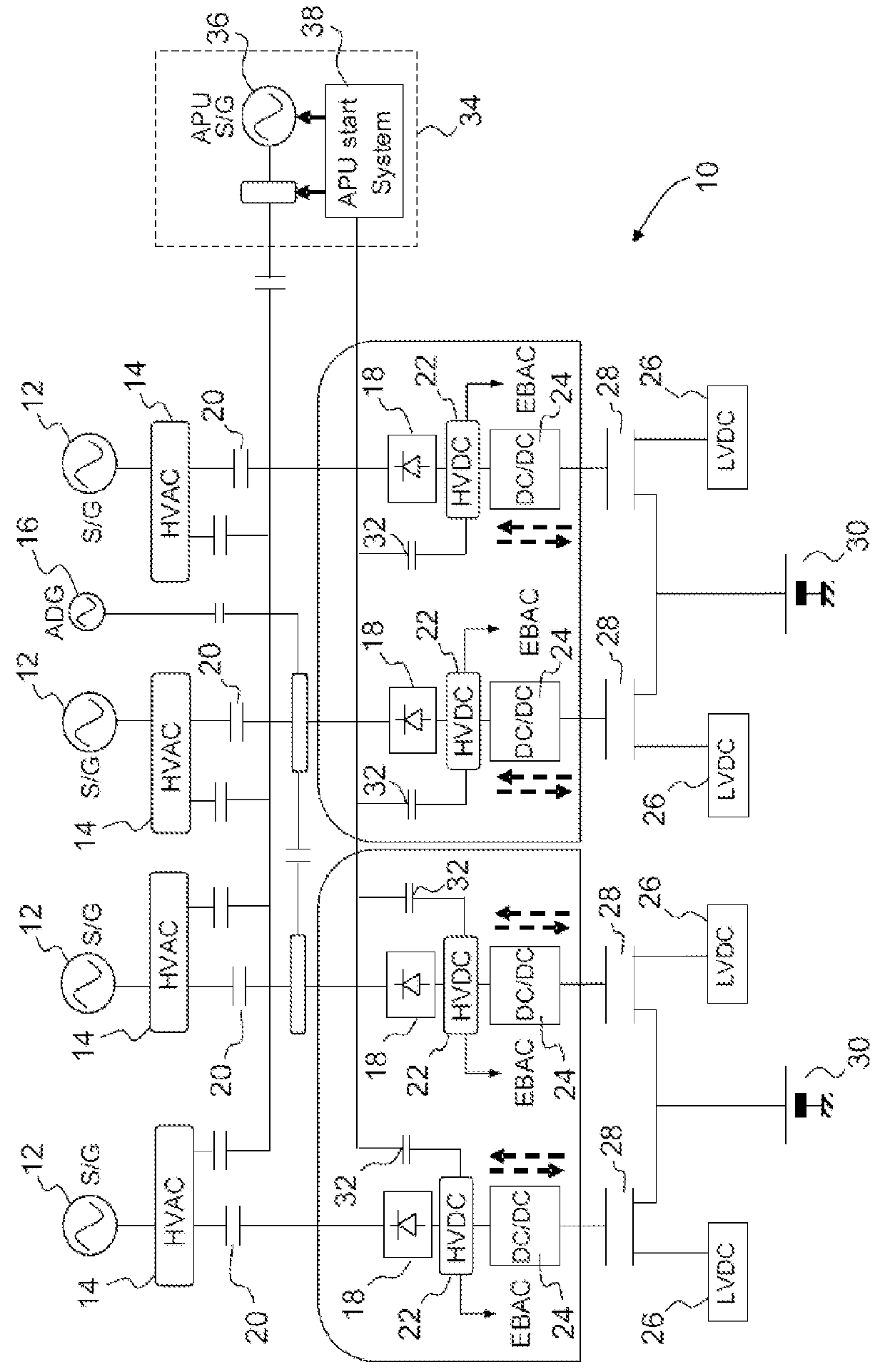
[0047]Generally speaking, in the following description of the present invention we shall distinguish two types of direct current network: high and low voltage, or HVDC and LVDC. The voltage most commonly used at present for HVDC networks is 540 V dc and it is 28 V dc for LVDC networks. Of course, the invention can be implemented regardless of the voltage values of these two types of network, the voltage of the high voltage network being greater than the voltage of the low voltage network.

Mutualisation of the Converters of the Network

[0048]FIG. 1 shows an example of an electrical network 10 according to the invention which can be implemented in a jumbo jet having four main generators 12 each one able to put out an alternating voltage of 230 V to a main network HVAC 14. An Air Driven Generator (ADG) 16 can also put out, as a last backup, an alternating voltage of 230 V. Each of the HVAC networks 14 is associated with a rectifier 18 across a contactor 20 to form four high voltage direc...


PUM


Abstract

An electrical network of an aircraft comprises: several main generators, several high voltage direct current networks powered by one of the generators in normal operation, several low voltage direct current networks powered by one of the high voltage direct current networks, several converters to transfer energy from one of the high voltage direct current networks to one of the low voltage direct current networks, the different converters being independent and isolated from each other, each converter being dedicated to one of the high voltage networks and to the low voltage direct current network, a load designed to be powered in normal operation by the main generators and in backup operation by one of the low voltage direct current networks, the backup operation being put into place when at least one of the high voltage networks is no longer powered by the associated main generator in normal operation.

Description

PRIOR ART OF THE INVENTION[0001]The invention concerns the conversion of electric power applied to aeronautical systems and more precisely the implementing of low voltage direct current onboard backup networks making use of batteries. Today, many airplanes use 28 V direct current or 28 V dc networks. These networks are known as LVDC from their abbreviation: Low Voltage Direct Current.[0002]The architecture of airplanes is evolving at present toward a broader use of electric energy. The need for a system of conversion and storage of energy is therefore also in the process of evolving due to the electrification of systems customarily utilizing pneumatic or hydraulic energy. The advent of new highly critical applications requiring operation from a normal and / or backup electrical source makes the structure of the electrical networks more complex. These new applications impose new constraints which are hard to reconcile with the current normal and backup electrical networks.[0003]High vo...

Claims


Application Information

Patent Timeline
Patent Type & Authority Applications(United States)
IPC IPC(8): H02J1/00B64D41/00H02M3/04H02M7/02
CPCH02J1/00B64D41/00H02M3/04H02M7/02H02J1/12H02J9/04H02J2310/44
Inventor LACAUX, FREDERICBRUZY, CHRISTOPHETHALIN, PASCAL
Owner THALES SA
Why Eureka
Try Eureka