

Power snake apparatus
a technology of power snakes and power rods, which is applied in the direction of sewer cleaning, transportation and packaging, and cleaning hollow objects, etc., can solve the problems of insufficient charge of batteries to complete the desired task, and achieve the effect of reducing the amount of lifting and carrying, facilitating the workload of operators, and enhancing the portability of devices
- Summary
- Abstract
- Description
- Claims
- Application Information
AI Technical Summary
Benefits of technology
Problems solved by technology
Method used
Image

Examples
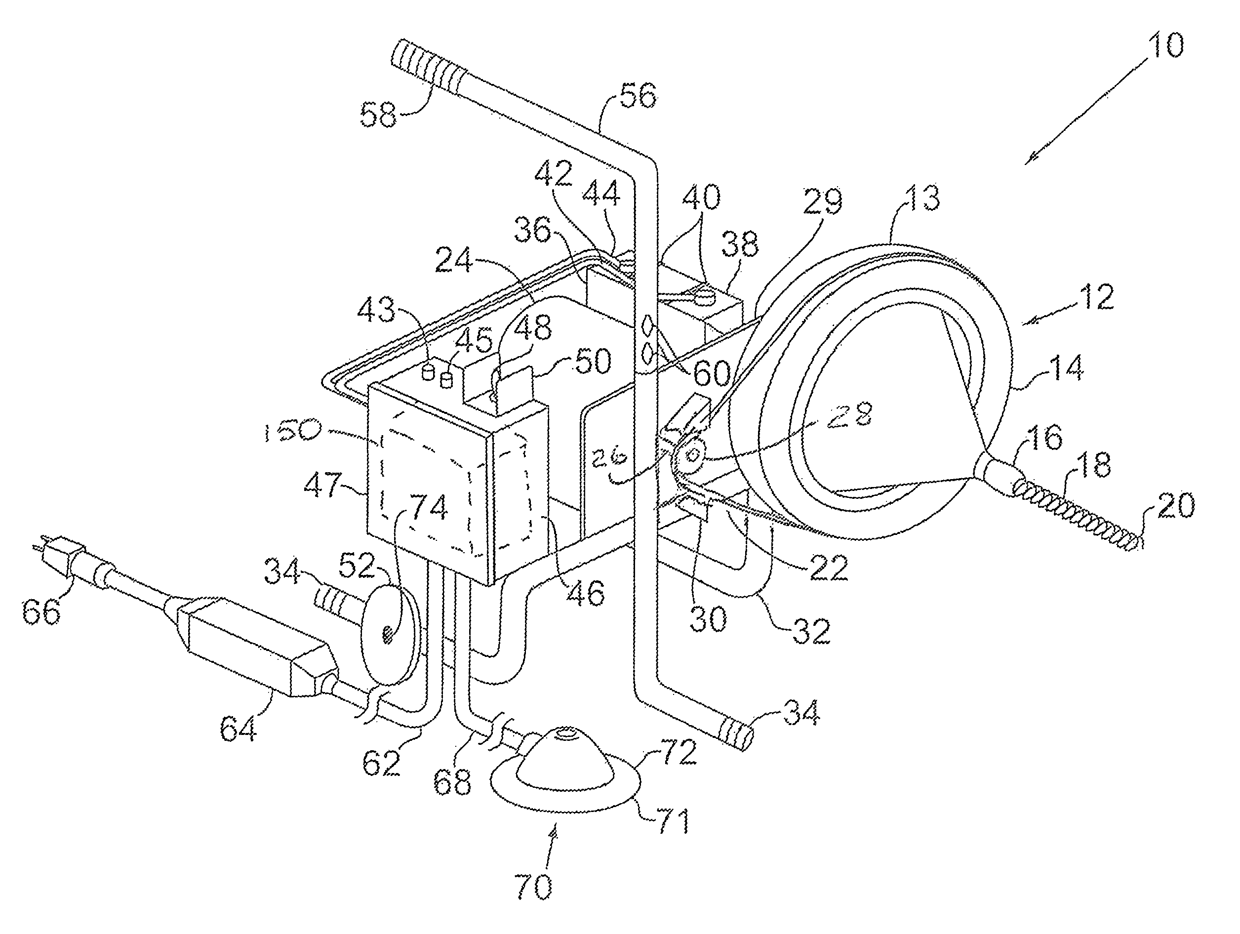
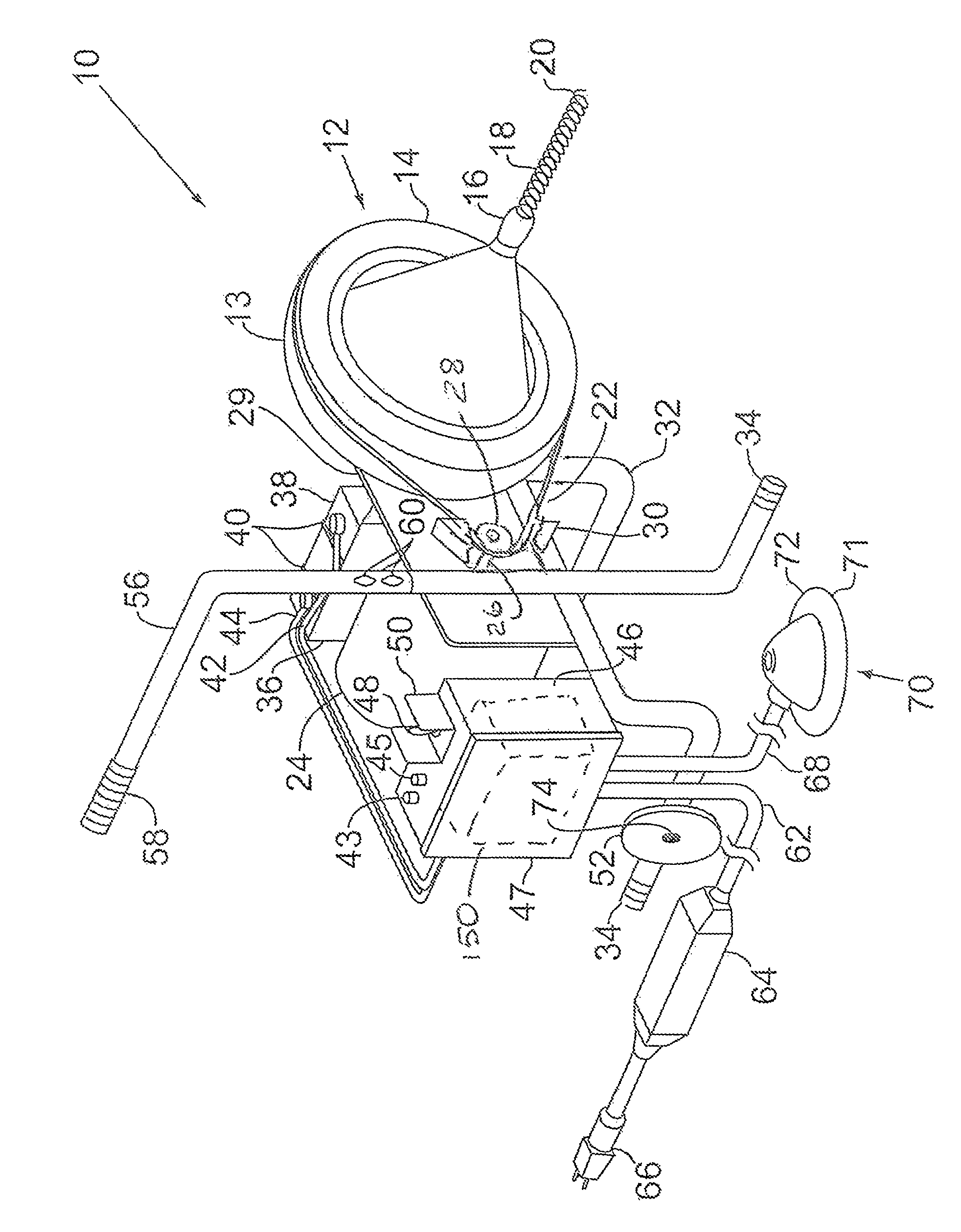
case 46
[0021]Electrical case 46 is enclosed by front face 47. Toggle switch 48 is a multi-position switch having “forward,”“reverse,” and “off” positions. Switch 48 is protected by switch guard 50.
[0022]Foot pedal 70 is attached to air switch 160 (located with electrical case 46) via air hose 68. Foot pedal 70 comprises a base 71 and air bladder 72. Foot pedal 70 is activated by applying pressure to air bladder 72, the pressure change in air hose 68 causing air switch 160 to engage (switch from the “off” position to the “on” position).
[0023]To operate the power snake 10, the unit is placed in the vicinity of a drain with a clog that requires removal. Drain cleaning cable 18 is pulled from drum 12 through annulus 16 and fed into the drain. Switch 48 is placed in the “forward” position, and foot pedal 70 is activated to engage motor 24. Motor 24 turns pulley wheel 28 and drum 12 via pulley cable 22. Rotation of drum 12 induces an equivalent rotation in drain cleaning cable 18 and cutter / auge...
PUM
 Abstract
Description
Claims
Application Information