

Web particle removal method and apparatus
- Summary
- Abstract
- Description
- Claims
- Application Information
AI Technical Summary
Problems solved by technology
Method used
Image

Examples
example 1
(Prior Art)
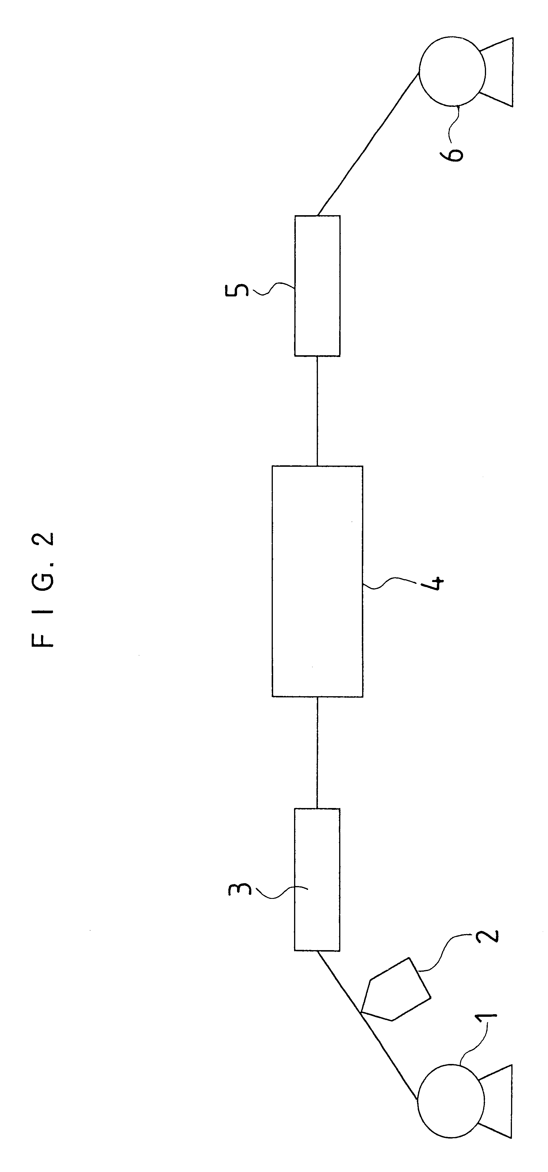
A transport apparatus in FIG. 2 fed a polyethyleneterephthalate film with a thickness of 100 .mu.m and a width of 100 cm at a speed of 50 m / min from a feeding apparatus 1. A coating head 2 coated the film with a coating liquid including latex with a mean particle size of 10 .mu.m. The coating liquid was dried in a first drying zone 1 to produce a film with a controlled deposit of foreign matter.
The composition of the coating liquid including the latex was as follows.
The undiluted latex solution included a monodisperse polyethylene latex of 1 weight %. The coating liquid of was applied on the film by 25 cm.sup.3 / m.sup.2. The dried film surface was observed through a microscope, and it was found that latex particles uniformly adhered to the film surface at a density of about 300 (particles) / m.sup.2.
Then, the film is guided to a wet process particle removal zone 4 in FIG. 2 without its coated surface being in contact with a roller and the like. A particle removal process wa...
example 2
(Prior Art)
A wet process particle removal was performed after adhering the latex particles as is the case with the example 1. In the example 2, an SUS304 blade for a blade coater with a length of 1.1 m along the width of the film and a tip thickness of 0.5 mm was attached along the width of the film instead of the rotary wire bar in the wet process particle removal zone 4 just after the fountain coater, which applied methanol on the film by 20 cm.sup.3 / m.sup.2.
A level C in FIG. 3 shows the results of the experiment. The number of residual latex particles was larger than that of the levels A and B, and the countless scratches were formed on the film surface.
example 3
(Comparative Art)
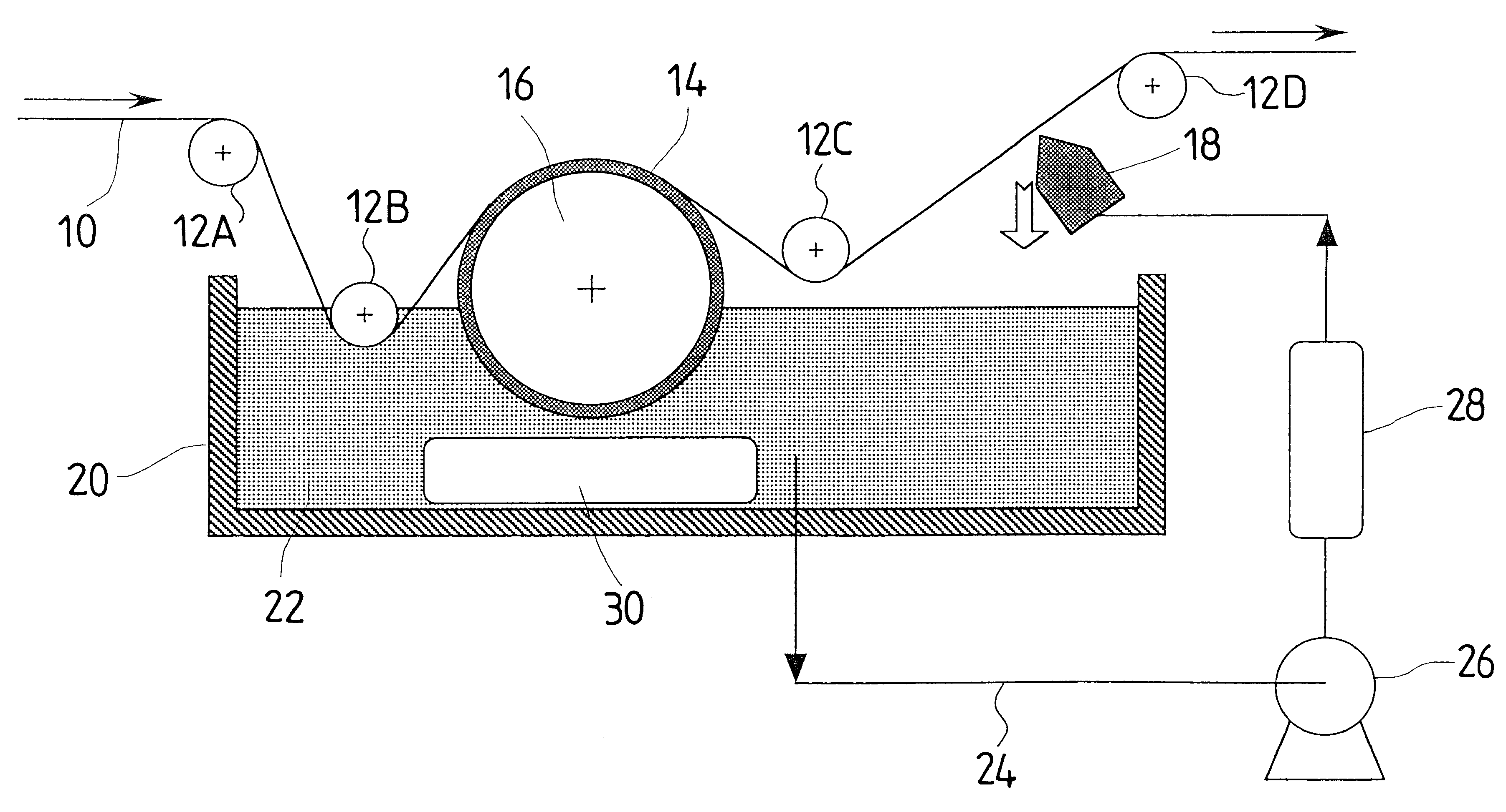
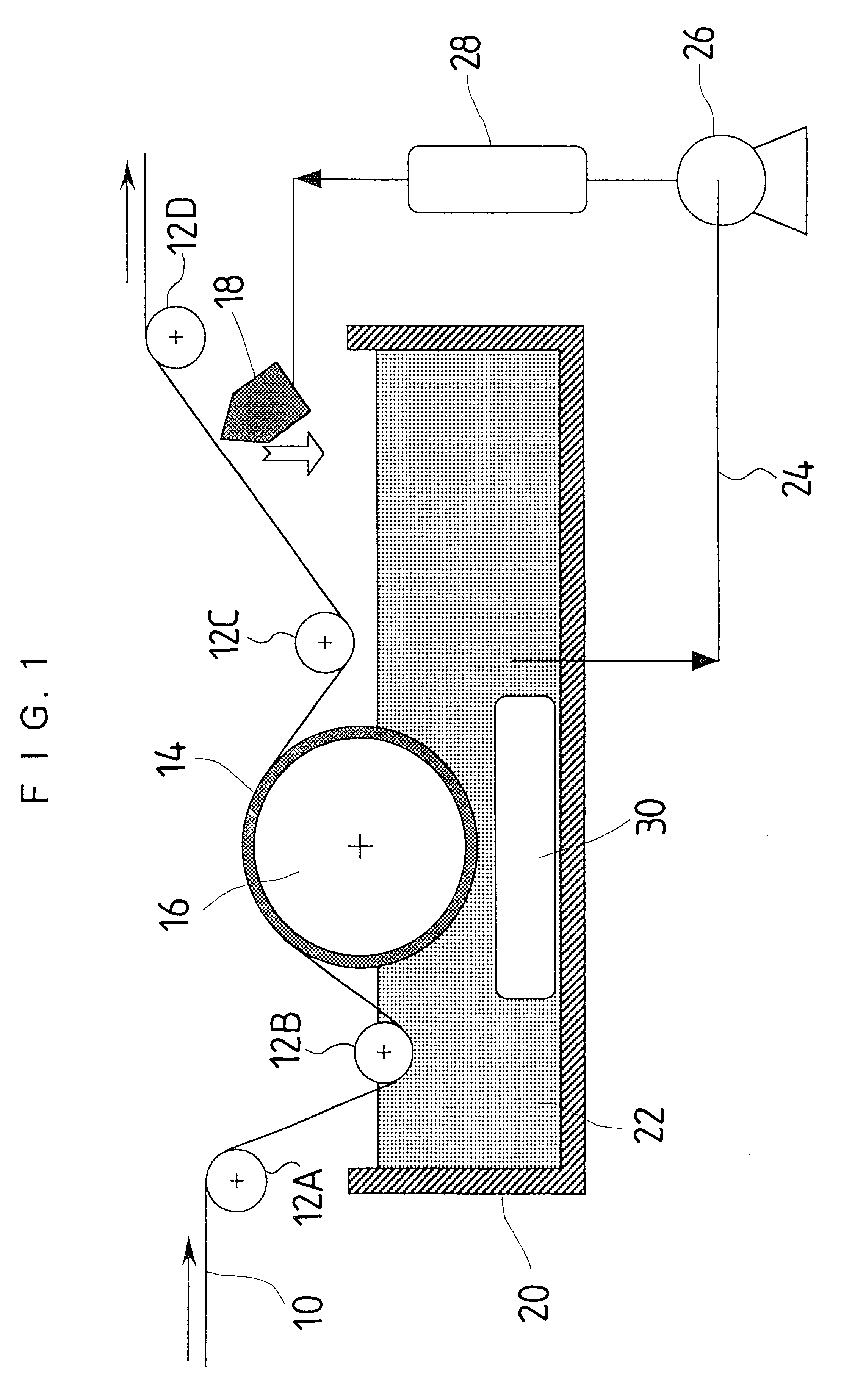
A wet process particle removal was performed after adhering the latex particles as is the case with the example 1. In the example 3, the surface of an aluminum roller with a length 1.1 m along the width of the film and a diameter of 20 cm was covered with fluorinated rubber with a thickness of 10 mm as shown in FIG. 1, and the roller was provided as the drive roller in the wet process particle removal zone 4 in FIG. 2. The guide rollers before and behind the drive roller were arranged so that the lap angle of the film with respect to the drive roller was 50 degrees, and the lower part of the drive roller coated with the fluorinated rubber was immersed by 10 cm in methanol. The drive roller was rotated in a reverse direction with respect to the film transport direction.
A level D and a level E in FIG. 3 show the results of experiments wherein the drive roller, which rotated at a speed of 10 rpm and a speed of 50 rpm, respectively. Compared with the prior arts of the l...
PUM
| Property | Measurement | Unit |
|---|---|---|
| Angle | aaaaa | aaaaa |
| Elasticity | aaaaa | aaaaa |
| Stress optical coefficient | aaaaa | aaaaa |
Abstract
Description
Claims
Application Information