Method for storing multiple levels of design data in a common database

a technology of logic design and database, applied in the field of digital logic design systems, can solve the problems of time-consuming and processor-intensive, improper connection or placement of physical items by designers within one or more cells,

Inactive Publication Date: 2003-01-07
MAGMA DESIGN AUTOMATION
View PDF30 Cites 355 Cited by
  • Summary
  • Abstract
  • Description
  • Claims
  • Application Information

AI Technical Summary

Benefits of technology

Another object of the present invention is to provide a system for automated logic circuit design which eliminates the need for translation of circuit descriptions between different design tools.
The above objects are achieved according to an aspect of the invention by providing an automated logic circuit design system which uses a common database to store design data at different states of the design process, including data-flow graphs, netlists and layout descriptions. In this way, the need to translate circuit descriptions between tools is eliminated, thus leading to increased speed, flexibility and integration. The common database includes entities, models, cells, pins, busses and nets. The data-flow graphs are stored as graphs, the nodes in a graph as cells, and the edges as busses. Physical design data is available by storing the cells in a model in a KD tree. This allows queries on cells in the netlist located in the layout within arbitrary areas.

Problems solved by technology

In many cases, the IC designer improperly connected or improperly placed a physical item within one or more cells.
This is time-consuming and processor-intensive (circuit specifications must be translated from one database format to another and another during the development process), disk-intensive (multiple databases each specifying the same circuit in different forms must be stored) and fragmented (tools cannot use the outputs of other tools, and a change to the circuit made by one tool is not reflected in the databases of the other tools).

Method used


Image

  • Method for storing multiple levels of design data in a common database
  • Method for storing multiple levels of design data in a common database
  • Method for storing multiple levels of design data in a common database

Examples


Embodiment Construction

First, given a Verilog description of a circuit to be developed, the Verilog must be parsed to generate a data flow graph suitable for implementation in the data model. RTL parsers known in the art are preferably used for this purpose. The output from the RTL parser is a Verilog parse tree which is used to generate the data flow graph. Although well-known in the art, the structure of the parse tree is relatively complicated and, since detailed knowledge of it is not necessary for an understanding of the present invention, further description of the parse tree will be omitted for simplicity and brevity.

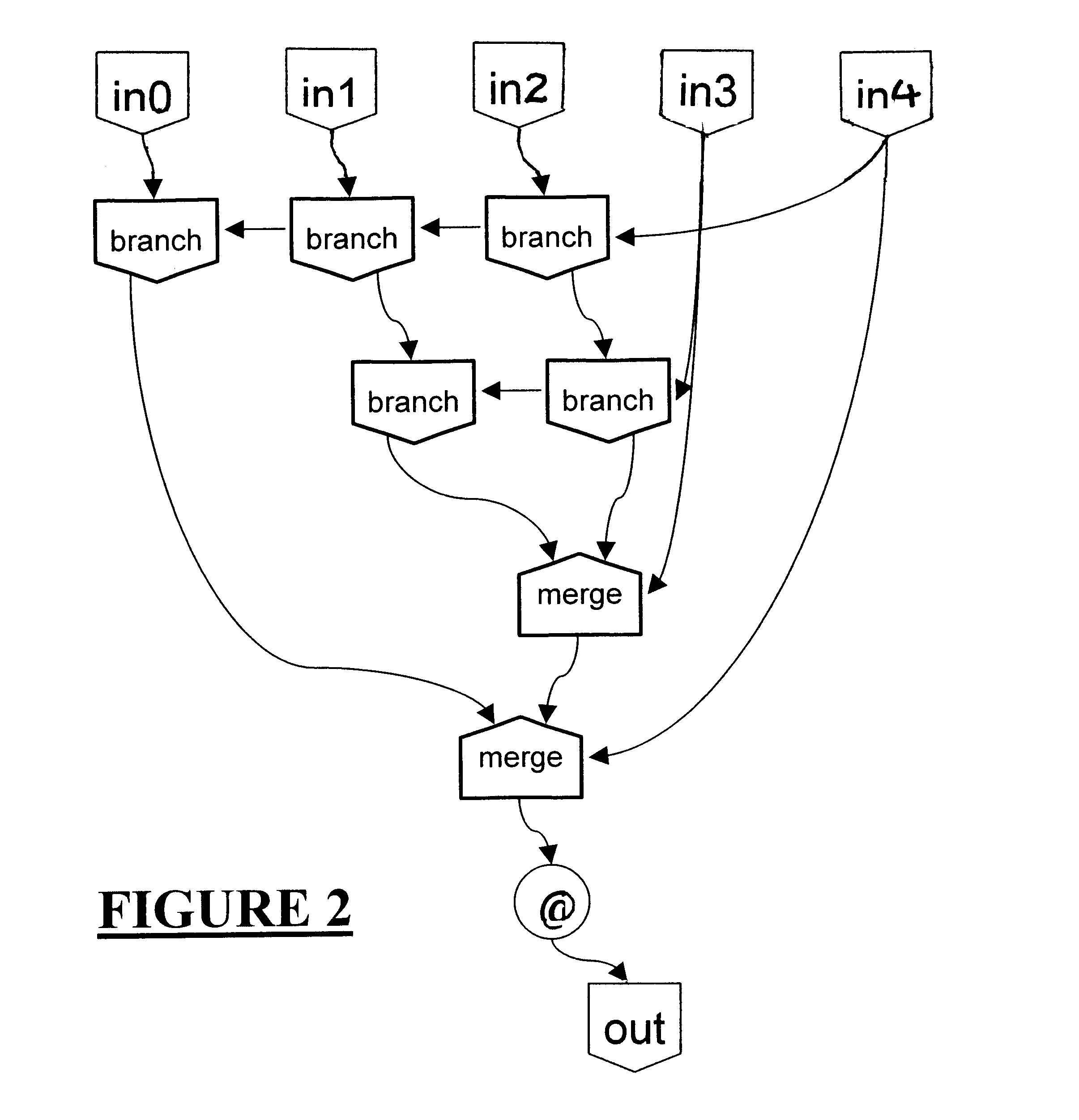
FIG. 1 shows an example of translation of the Verilog source code

always @(posedge clk)

begin

out=in1+in2;

if (c)

out=in3;

end

into data flow elements. Here, in0, in1, in2, c and clk are input ports of an Entity (described below) and out is an output port of the Entity. An adder (an example of a Cell as described bellow) adds the values at Ports in0 and in1 and supplies the result to a merge ...


PUM


Abstract

An automated logic circuit design system uses a common database to store design data at different states of the design process, including data-flow graphs, netlists and layout descriptions. In this way, the need to translate circuit descriptions between tools is eliminated, thus leading to increased speed, flexibility and integration. The common database includes entities, models, cells, pins, busses and nets. The data-flow graphs are stored as graphs, the nodes in a graph as cells, and the edges as busses. Physical design data is available by storing the cells in a model in a KD tree. This allows queries on cells in the netlist located in the layout within arbitrary areas.

Description

1. Field of the InventionThe present invention is directed to digital logic design systems. More particularly, the invention is directed to automated digital logic synthesis and placement systems.2. Background of the Related ArtPrior art computer aided design (CAD) systems for the design of integrated circuits and the like assist in the design thereof by providing a user with a set of software tools running on a computer. In the prior art, the process of designing an integrated circuit on a typical CAD system was done in several discrete steps using different software tools.First, a schematic diagram of the integrated circuit is entered interactively to produce a digital representation of the integrated circuit elements and their interconnections. This representation may initially be in a hardware description language such as Verilog and then translated into a register transfer level (RTL) description in terms of pre-designed functional blocks, such as memories and registers. This m...

Claims


Application Information

Patent Timeline
Patent Type & Authority Patents(United States)
IPC IPC(8): G06F17/50H01L21/82
CPCG06F17/5045G06F17/5068G06F17/505G06F30/327G06F30/30G06F30/39
Inventor VAN GINNEKEN, LUKAS P. P. P.GROENEVELD, PATRICK R.PHILIPSEN, WILHELMUS J. M.
Owner MAGMA DESIGN AUTOMATION
Why Eureka
Try Eureka