Vacuum flush assist system and process for handling machining cutting fluid

Inactive Publication Date: 2003-01-21
FILTRA SYSTEMS COMPANY
View PDF12 Cites 29 Cited by
  • Summary
  • Abstract
  • Description
  • Claims
  • Application Information

AI Technical Summary

Benefits of technology

The sumps can continue to drain into the header pipe during a fluid cycle, but any sump drain may be closed off when the fluid level in that sump declines below a certain minimum level to prevent any air from entering the header pipe during the flush cycle to maintain the vacuum acting on

Problems solved by technology

This requires a fairly steep slope such that the trench becomes quite deep if a long run is involved.
Floor trenches are quite costly to construct, particularly if a double lining is required by environmental regulations, as hidden leaks are a problem as they may exist for long periods, allowing the oil containing cutting fluids to pollute the ground water.
In addition, concrete lined trenches below grade make plant revisions more costly and difficult since such trenches cannot be relocated.
Flushing jets are som

Method used


Image

  • Vacuum flush assist system and process for handling machining cutting fluid
  • Vacuum flush assist system and process for handling machining cutting fluid
  • Vacuum flush assist system and process for handling machining cutting fluid

Examples


Embodiment Construction

In the following detailed description, certain specific terminology will be employed for the sake of clarity and a particular embodiment described in accordance with the requirements of 35 USC 112, but it is to be understood that the same is not intended to be limiting and should not be so construed inasmuch as the invention is capable of taking many forms and variations within the scope of the appended claims.

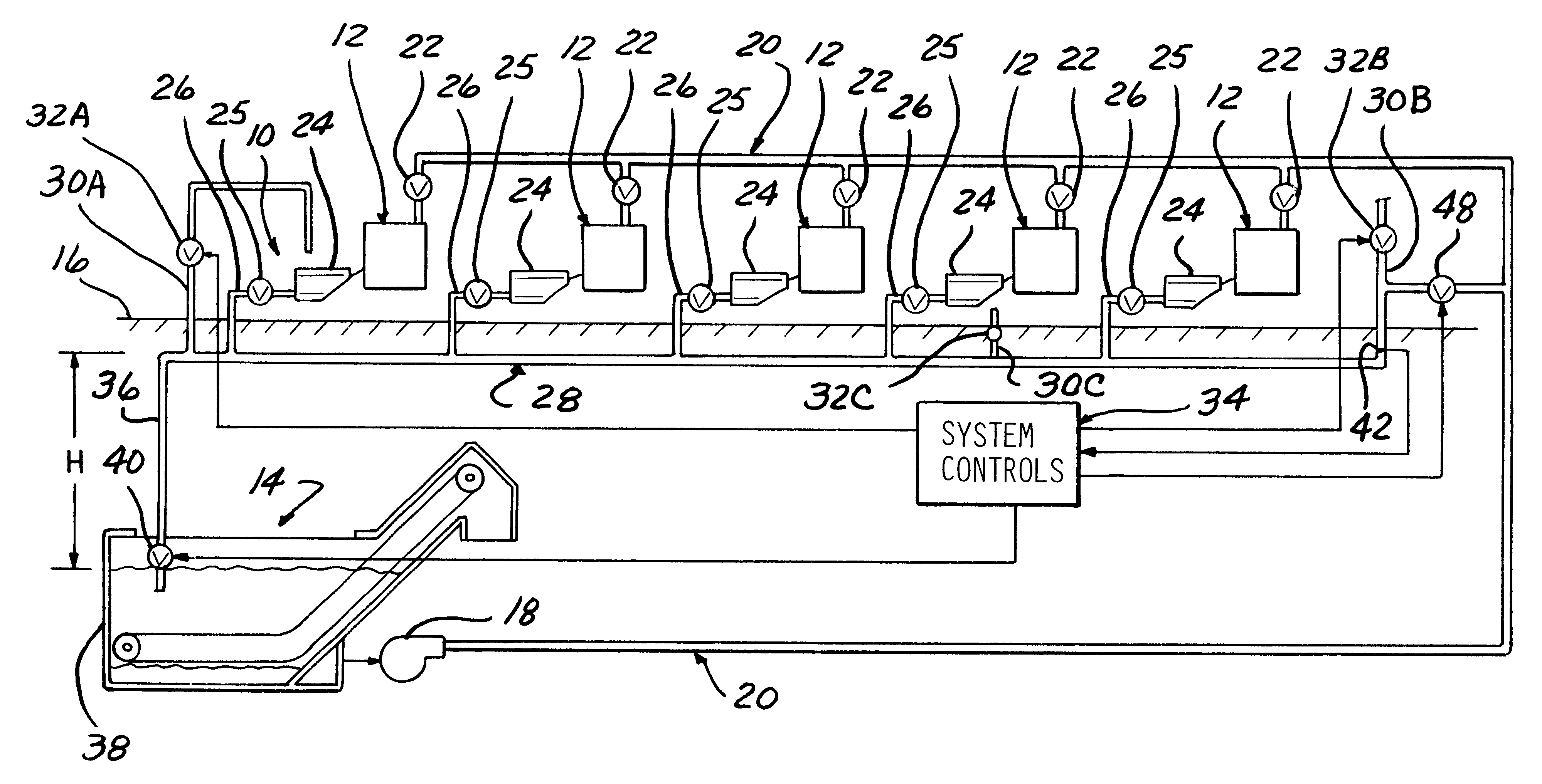
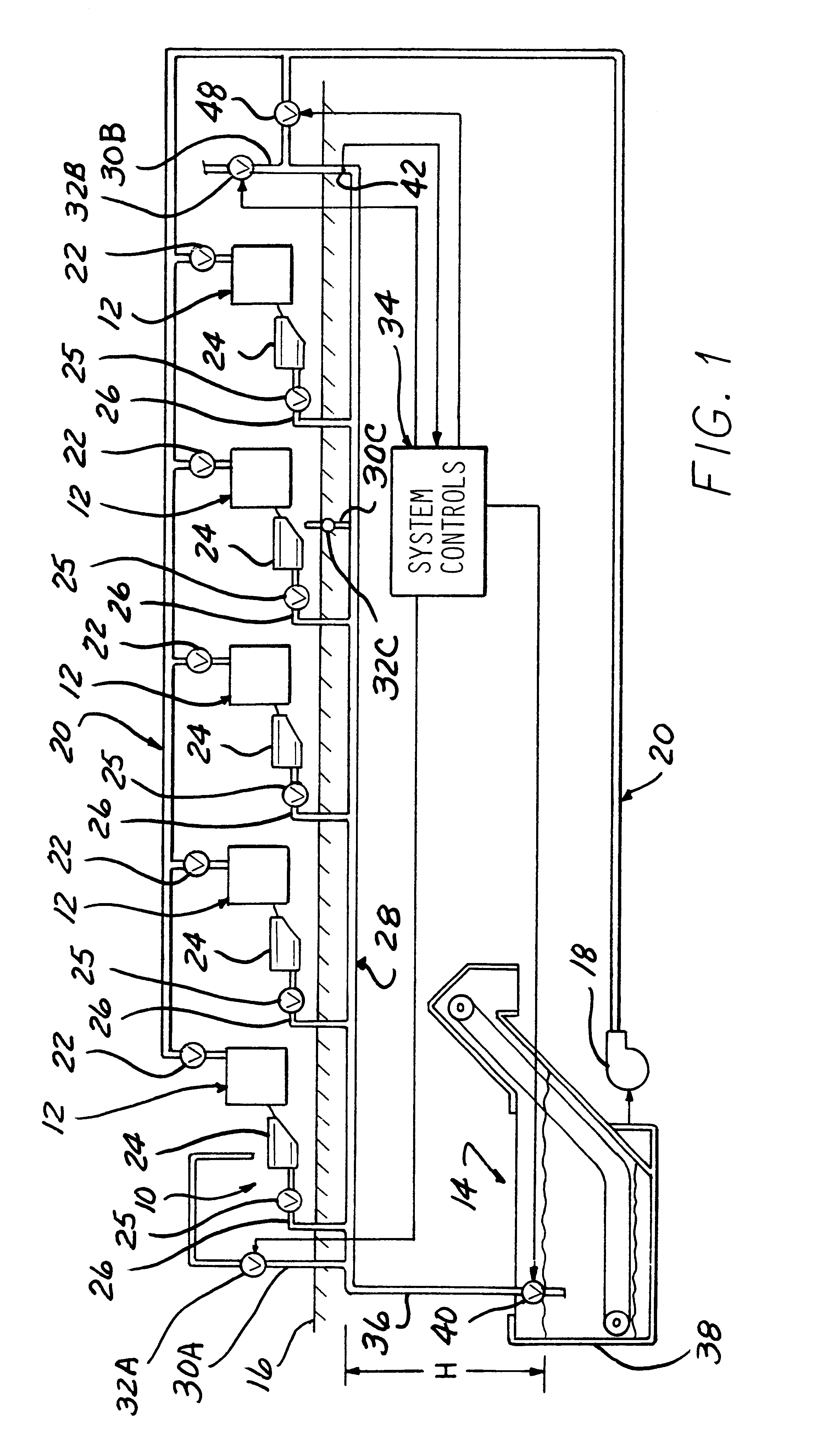
Referring to FIG. 1, a vacuum assist flush collector system 10 is shown associated with a series of machine tools 12, depicted in block diagram form.

Filtration apparatus 14 is of a well known type disposed in a pit located below floor grade indicated by line 16. The filtration apparatus 14 includes an open tank 38 receiving cutting fluid from the machine tools 12 collected by the handling system 10, filters the same and a pump 18 returns clean fluid via piping 20 to the machine tools 12 for reuse. The supply of clean cutting fluid to each machine tool 12 may be controlled by v...


PUM

PropertyMeasurementUnit
Distanceaaaaaaaaaa
Diameteraaaaaaaaaa
Levelaaaaaaaaaa

Abstract

A vacuum assist system and process for handling cutting fluid and chips collected from a series of machine tools includes a closed header pipe extending below a series of sumps associated with the machine tools, the sumps draining into the header pipe. The header pipe has a down leg extending vertically down to a filter tank which is opened periodically to drain the header pipe, developing a vacuum which assists the flow of liquid down the header pipe so as to insure a sufficient flow velocity in the header pipe to carry the collected chips out of the header pipe and into the filter tank with the cutting fluid.

Description

BACKGROUND OF THE INVENTIONThis invention concerns the handling of cutting fluid used in the machining of metal parts to enable the cutting fluid to be filtered and reused.In a typical installation, the cutting fluid containing chips and other debris is deposited in a trench extending below the machine tools. The flow of cutting fluid is designed to carry the chips, and other debris down the trench to a pit where filtration apparatus cleans the cutting fluid for reuse.In order to insure that the chips are carried down the trench, a certain flow velocity is necessary, i.e., 7 ft / sec. is a typical minimum flow velocity with iron or steel chips. This requires a fairly steep slope such that the trench becomes quite deep if a long run is involved. Floor trenches are quite costly to construct, particularly if a double lining is required by environmental regulations, as hidden leaks are a problem as they may exist for long periods, allowing the oil containing cutting fluids to pollute the ...

Claims


Application Information

Patent Timeline
IPC IPC(8): B23Q11/00B23Q11/10B01D17/12
CPCB23Q11/0046B23Q11/1069B23Q11/10B01D2201/204Y10T409/303752Y10T409/304088Y10T137/8634Y10T137/87684Y02P70/10
Inventor BRATTEN, JACK R.
Owner FILTRA SYSTEMS COMPANY
Why Eureka
Try Eureka