Internal combustion engine with variable compression ratio mechanism

a technology of compression ratio and internal combustion engine, which is applied in the direction of combustion engine, crankshaft bearing, crankshaft bearing, etc., can solve the problem of providing the engine with a compact construction

Inactive Publication Date: 2003-01-28
NISSAN MOTOR CO LTD
View PDF6 Cites 34 Cited by
  • Summary
  • Abstract
  • Description
  • Claims
  • Application Information

AI Technical Summary

Benefits of technology

It is another object of the present invention to provide a variable compression ratio mechanism which can be compactly installed in an internal combustion engine.
According to the present invention, there is provided an internal combustion engine which comprises a cylinder block having a cylinder in which a piston reciprocates; a crankshaft rotatably installed in the cylinder block and including a crank pin and a counter-weight; and a variable compression ratio mechanism including an upper link having one end pivotally connected to a piston pin of the piston, a lower link pivotally disposed on the crank pin of the crankshaft and having one part pivotally connected to the other end of the upper link, a control shaft extending substantially in parallel with the crankshaft, a control link having a first end pivotally connected to the other part of the lower link and an eccentric bearing structure through which a second end of the control link is connected to the control shaft, so that rotation of the control shaft about its axis induces a pivoting of the lower link about said crank pin thereby to vary the stroke of the piston.

Problems solved by technology

However, due to its inherent construction, the variable compression ratio mechanism of the above-mentioned type has failed to provide the engine with a compact construction.

Method used


Image

  • Internal combustion engine with variable compression ratio mechanism
  • Internal combustion engine with variable compression ratio mechanism
  • Internal combustion engine with variable compression ratio mechanism

Examples


first embodiment

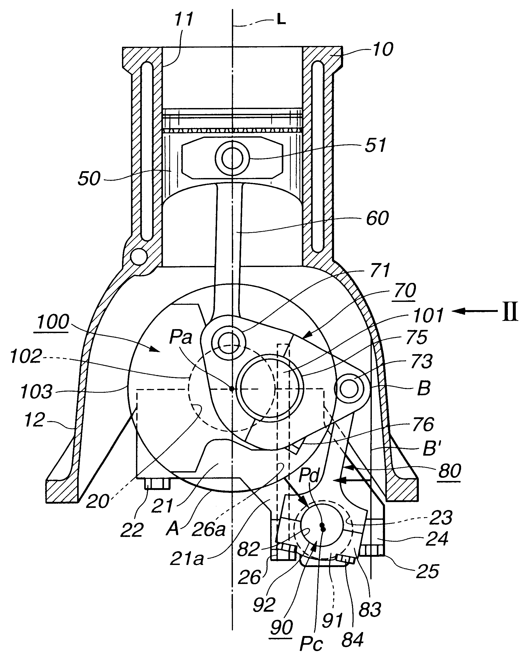
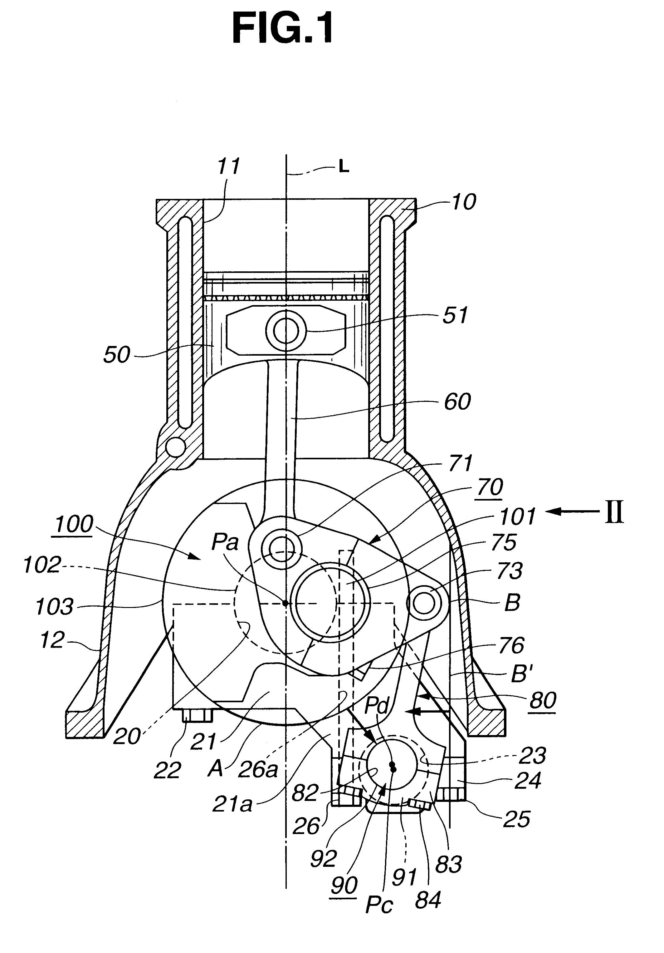
Referring to FIGS. 1 to 4, there is shown an internal combustion engine with a variable compression ratio mechanism, which is the present invention.

The engine having the variable compression ratio mechanism incorporated therewith is of a four cylinder type.

As is well seen from FIGS. 1 and 2, the variable compression ratio mechanism comprises four upper links 60 each having one end pivotally connected to a piston pin 51 of a corresponding piston 50, four lower links 70 each being pivotally disposed on a crank pin 101 of a crankshaft 100 and having one end pivotally connected through an upper link pin 71 to the other end of the corresponding upper link 60, a control shaft 90 located at a right lower side of the crankshaft 100 (in FIG. 1) and extending in parallel with the crankshaft 100 and four control links 80 each having a lower end pivotally connected, through an aftermentioned eccentric bearing structure, to the control shaft 90 and an upper end pivotally connected through a cont...

second embodiment

Referring to FIGS. 12 to 14, there is shown an internal combustion engine of the present invention.

In this second embodiment, to each of the bearing caps 21A for the crankshaft 100, there is integrally connected the bearing portion 23 for the control shaft 90. That is, as is seen from FIG. 13, the bearing cap 21A is integral with the bearing portion 23. Unlike in the above-mentioned first embodiment, the bearing portion 23 has not a split structure, and thus in the second embodiment, there are no members corresponding to the bearing caps 24 and the connecting bolts 25 which are used in the first embodiment. Although the facility of assembling the control shaft 90 to the bearing portion 23 is somewhat poor as compared with the first embodiment, reduction in number of parts and simplification of the construction are achieved in the second embodiment.

third embodiment

Referring to FIGS. 15 to 17, there is shown an internal combustion engine of the present invention.

In this third embodiment, to lower surfaces of the bearing caps 21B, there is secured a bearing beam 30. As is seen from FIG. 17, the bearing beam 30 comprises a plurality of branch plate portions 35 which are secured to the lower surfaces of the bearing caps 21B and an elongate base plate portion 34 which connects the branch plate portions 35 integrally.

As is seen from FIG. 16, the bearing beam 30 is formed with bearing portions 31 for the control shaft 90. Each bearing portion 31 has a split structure for facilitating the work for assembling the control shaft 90 thereto. That is, each bearing portion 31 comprises a rounded recess formed in a lower surface of the branch plate portion 35 of the bearing beam 30 and a rounded recess formed in an upper surface of a bearing cap 32 which is bolted to the lower surface of the branch plate portion 35.

As is understood from FIG. 17, the bearing...


PUM


Abstract

An internal combustion engine is constructed to include a variable compression ratio mechanism. The mechanism has the following structure. An upper link has one end pivotally connected to a piston pin of a piston of the engine. A lower link is pivotally disposed on a crank pin of a crankshaft of the engine and has one part pivotally connected to the other end of the upper link. A control shaft extends substantially in parallel with the crankshaft. A control link has an end pivotally connected to the other part of the lower link. The other end of the control link is connected to the control shaft through an eccentric bearing structure, so that rotation of the control shaft about its axis induces a pivoting of the lower link about the crank pin varying the stroke of the piston.

Description

1. Field of the InventionThe present invention relates in general to internal combustion engines having a variable compression ratio mechanism by which the compression ratio of the engine can be varied, and more particularly to internal combustion engines having the variable compression ratio mechanism of a double-link type.2. Description of the Prior ArtIn order to clarify the task of the present invention, one known internal combustion engine of the above-mentioned type will be briefly described with reference to FIG. 42 of the accompanying drawings, which is shown in a paper "MTZ Motortechnische Zeitschrift 58" issued in 1997 in Germany.As shown in the drawing, the engine having a variable compression ratio mechanism incorporated therewith is of a four cylinder type.The mechanism comprises four upper links 2 each having one end pivotally connected to a piston pin 1a of a corresponding piston 1, four lower links 4 each being pivotally disposed on a crank pin of a crankshaft 3 and ...

Claims


Application Information

Patent Timeline
Patent Type & Authority Patents(United States)
IPC IPC(8): F02B75/00F02B75/04F02B23/00F02D15/02F02F7/00F16C3/06F16C9/02
CPCF02B75/045F02B75/048F02F2007/0056
Inventor FUJIMOTO, HIROYAMOTEKI, KATSUYA
Owner NISSAN MOTOR CO LTD
Why Eureka
Try Eureka