Energized sealing cartridge for annulus sealing between tubular well components

a technology of annulus sealing and sealing cartridge, which is applied in the direction of sealing/packing, hose connection, borehole/well accessories, etc., can solve the problems of inability to deform into and establish efficient sealing with the surface pit, fissures and other irregularities of the surface irregularities of the outer peripheral well casing surface, and not a practical consideration

Inactive Publication Date: 2003-01-28
FMC TECH INC
View PDF9 Cites 66 Cited by
  • Summary
  • Abstract
  • Description
  • Claims
  • Application Information

AI Technical Summary

Problems solved by technology

However, the increasing trend towards drilling deep wells into relatively high pressure strata, and the frequency of encountering hydrogen sulfide or other dangerous or corrosive gases in these wells, has led to development of packoffs with all metal seal elements to establish a metal-to-metal pressure barrier.
This is not a practical consideration when elastomer seals are employed or when metal sealing elements lack sufficiently high setting force to accommodate the geometric non-conformity of the well casing.
Even further, when the outer peripheral surface of the well casing is rough, which is often the case, metal-to-metal annulus sealing between the tubular elements can be exceedingly difficult due to the lack of sufficiently high setting force of the metal seals for adequate sealing with the rough surface of the casing.
Another difficulty of metal-to-metal sealing under these conditions is that the metal sealing elements are typically formed of hard metal, and thus are incapable of deforming into and establishing efficient sealing with the surface pits, fissures and other surface irregularities of the outer peripheral well casing surface.
Of course, the well casing can be machined to form a relatively smooth outer peripheral surface to facilitate effective sealing, but the difficulty and expense of machining a portion of a well casing cause machining of the well casing to be a commercially impractical solution to the problem.

Method used


Image

  • Energized sealing cartridge for annulus sealing between tubular well components
  • Energized sealing cartridge for annulus sealing between tubular well components
  • Energized sealing cartridge for annulus sealing between tubular well components

Examples


Embodiment Construction

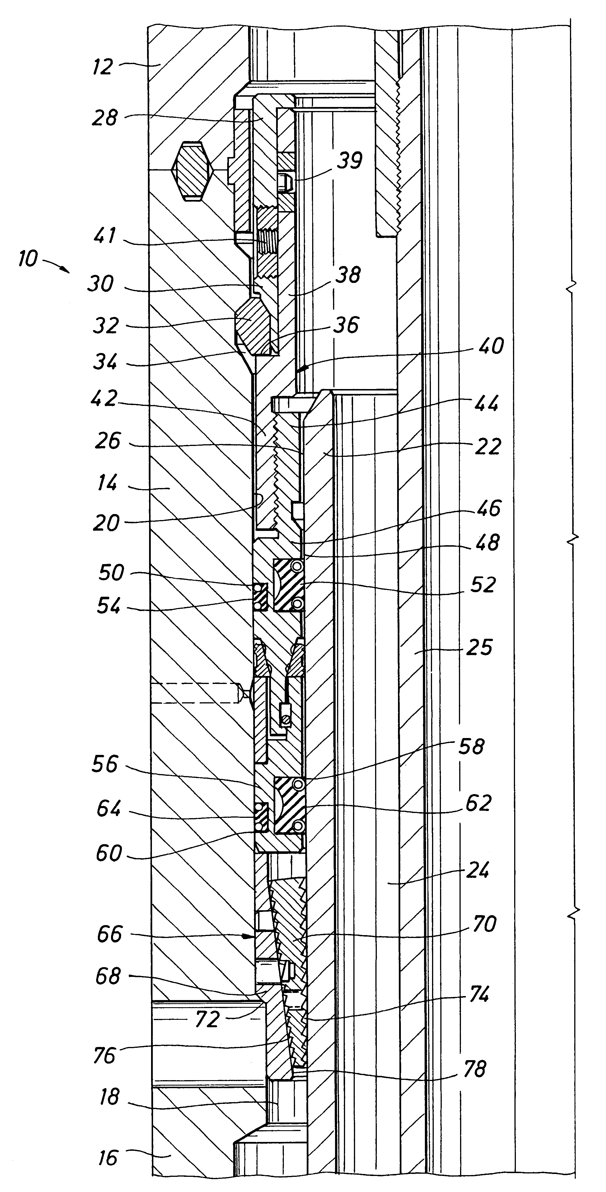
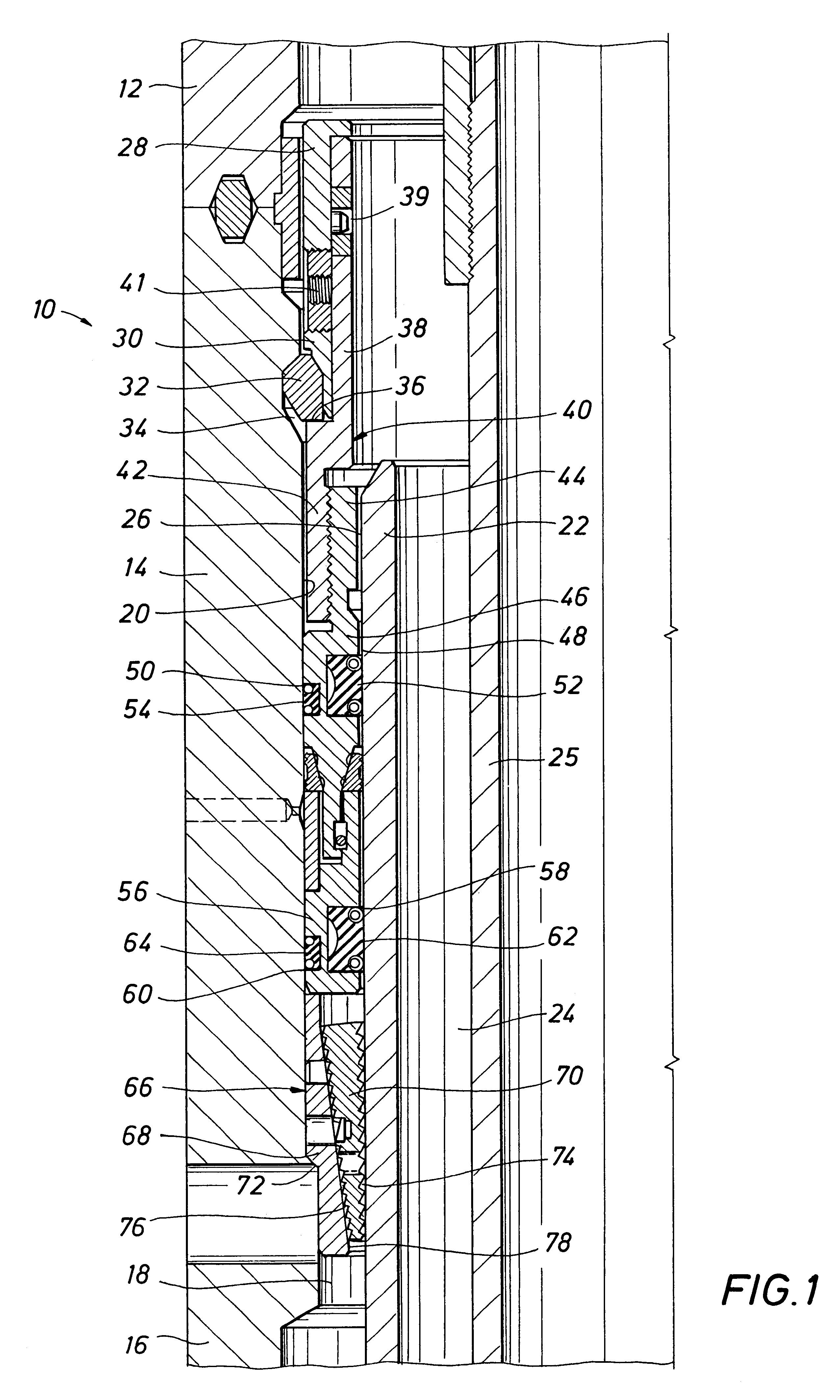
Referring now to the drawings and first to FIG. 1, a wellhead assembly of conventional nature is shown generally at 10 and has a tubular wellhead housing 11 having upper, intermediate and lower wellhead housing sections 12, 14 and 16 which are connected or otherwise maintained in sealed assembly. Regarding the wellhead housing, it is not necessary that the specific wellhead arrangement shown in the drawings be employed in order to practice the invention. The tubular wellhead housing defines an internal wellhead seal bore 18 having an internal cylindrical sealing surface 20. The sealing surface 20 is typically machined so that it is smooth so that sealing with it is relatively simple and efficient. Within the wellhead bore is typically supported the upper end of a section of well casing 22 which defines a casing bore 24 and also defines an outer peripheral surface 26 of generally cylindrical configuration. Within the casing bore 24 is typically located a tubing string 25, which may b...


PUM


Abstract

A mechanically energized annular packoff seal cartridge for metal-to-metal sealing with substantially concentrically arranged tubular members, such as the tubular wellhead housing and well casing of an oil and gas well. A tubular pressure responsive energizing mandrel having downwardly converging frusto-conical seal actuating surfaces is of a dimension for entry into the annulus between the wellhead seal bore and the rough outer surface of the well casing. Elastomer seals are carried by the energizing mandrel and establish sealing of the energizing mandrel with the wellhead housing and well casing A pair of soft metal seal rings are carried by the seal cartridge and are forced radially into metal-to-metal sealing with the wellhead housing and the rough outer surface of the well casing respectively by the double tapered seal actuating surfaces responsive to pressure induced downward force on the energizing mandrel. A locking mandrel and the seal actuating mechanism are restrained against actuating movement during running of the seal cartridge by a running tool by shear pins, thus enabling the cartridge to pass through various well equipment. The shear pin of the locking mandrel is sheared by downward force applied by the running tool to lock the seal cartridge within the wellhead housing. The shear pin of the seal actuating mechanism is sheared, after locking of the cartridge to the wellhead housing, by the force of pressure introduced into the wellhead above the seal cartridge which acts to develop a pressure differential across the elastomer seals of the cartridge.

Description

1. Field of the InventionThe present invention relates generally to sealing mechanisms for sealing between tubular elements such as between a rough casing and the wellhead seal bore of a wellhead assembly. More particularly, the present invention concerns a mechanically energized seal cartridge for metal-to-metal sealing and elastomer sealing between substantially concentrically arranged tubular element for sealing the annulus therebetween.2. Description of the Prior ArtIn the oil and gas industry, and especially in subsea or other underwater well drilling procedures, it is well established practice to employ an annular seal assembly, referred to as a packoff, between adjacent concentric wellhead elements such as the wellhead seal bore and rough well casing or between a wellhead housing and casing hangers that support the casing strings in the well, to pressure seal the annuli between these elements. For many years these packoffs have included elastomeric or other non-metallic annul...

Claims


Application Information

Patent Timeline
Patent Type & Authority Patents(United States)
IPC IPC(8): E21B33/03E21B33/043E21B33/00
CPCE21B33/043E21B2033/005E21B2200/01
Inventor KOLEILAT, BASHIR M.CAIN, DAVID E.ZHENG, QIU SHIHUNT, MICHAEL
Owner FMC TECH INC
Why Eureka
Try Eureka