Printer assembly and printer

Inactive Publication Date: 2003-01-28
F&F
View PDF8 Cites 12 Cited by
  • Summary
  • Abstract
  • Description
  • Claims
  • Application Information

AI Technical Summary

Benefits of technology

As the non-roller type, it is desired to have a section of a shape tapered toward the thermal head, not a circular shape, such as a semi-circular shape or a trapezoidal shape with the thermal head side becoming narrow. The one side of such shape of platen can be supported easily by a housing or the like, and the other side is pushed against the thermal head. Therefore, adopting an elastic body having the section of above as the platen, reliably apply a predetermined force for pressure to the printing paper. In addition, it is preferable that at least a portion facing the line thermal head is covered with a covering material having a low coefficient of friction, for example, a fluoro resin type material such as Teflon (trademark). By the platen of this invention, a force for pressing the thermal paper against the thermal head can be obtained and the frictional resistance at the time of paper feed can be made small even with the non-roller type platen.
In the platen having the plate pressing against the line thermal head with an elastic member, by depressing the plate or the elastic member, it is possible to make the gap between the platen and the thermal head.

Problems solved by technology

Moreover, in a case where a computer is used for daily work such as electronic commerce / transactions or the like, the quantity of information to be printed out is small, and the frequency of using a printer may be low.
However, in order to realize a printer having a thickness of about 10 mm or less, a mechanism for pushing a printing paper against the thermal head becomes a big problem.
To realize a thin printer, it is necessary to reduce the diameter of the platen roller, but if the diameter of the platen roller is made small, the contact area becomes insufficient.
However, if the diameter of the platen roller is made 10 mm or less, the strength of the platen roller becomes insufficient, hence if a pushing force or pressure is increased, distortion or bend is likely to occur.
Moreover, if the diameter of the platen roller becomes 5 mm or less, distortion occurs, hence the platen roller cannot push the printing paper against the thermal head with a uniform force.
In particular, when the printer is a line thermal printer, if a force for pressing the thermal paper against the line thermal head differs in the paper width direction, or if a pressure is partly insufficient, the printing quality is deteriorated, and printing becomes impossible.
In the case of a platen roller, however, since it is necessary to apply a uniform pressure in the scanning direction, that is longitudinal direction of the roller, the roller cannot be divided in the longitudinal direction.
Hence, the above solution cannot be adapted to the platen roller.
However, additional thickness is required for installing the sub rollers, hence the second solution is not adaptable to a thin printer.

Method used


Image

  • Printer assembly and printer
  • Printer assembly and printer
  • Printer assembly and printer

Examples


Embodiment Construction

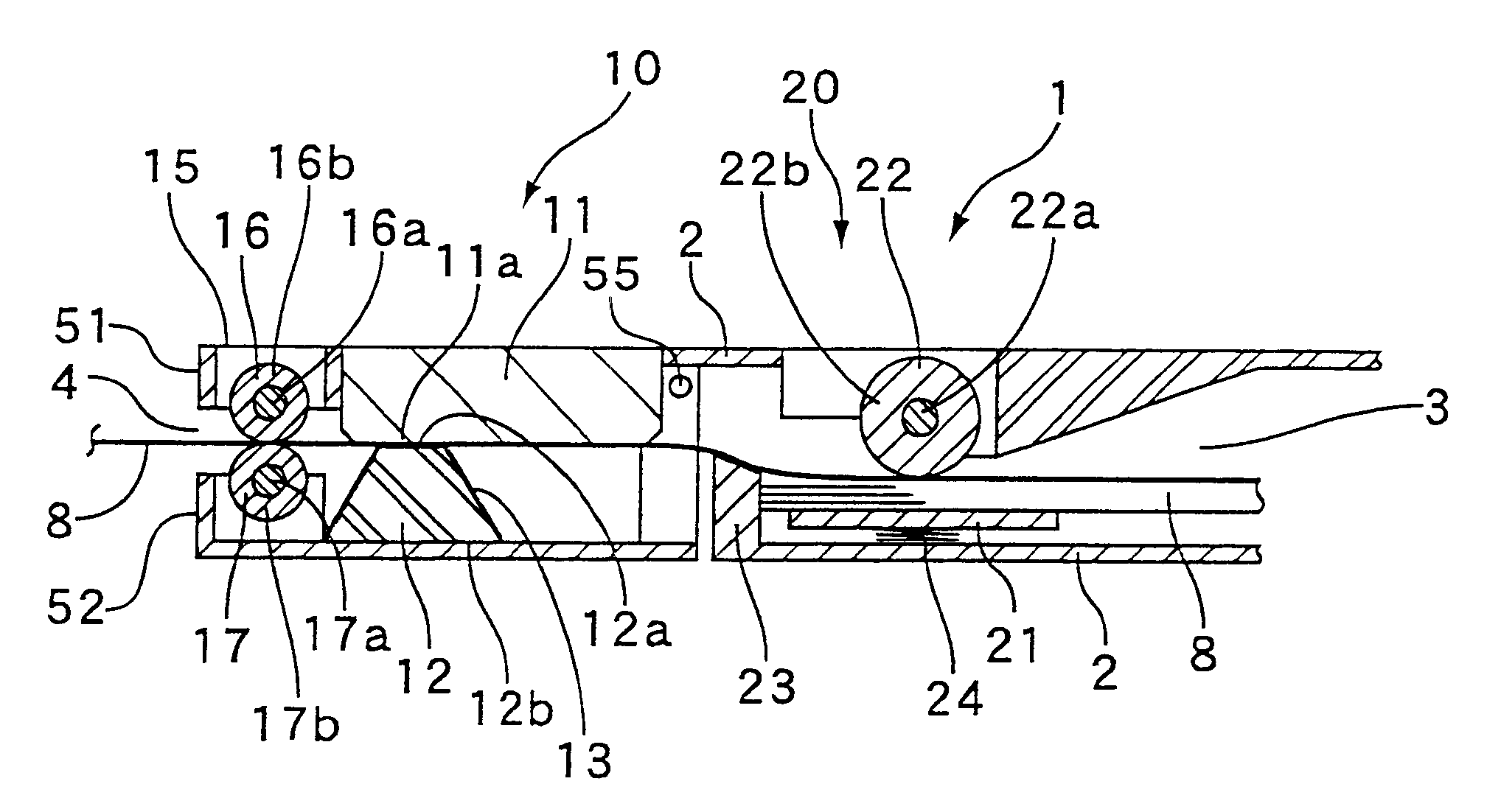
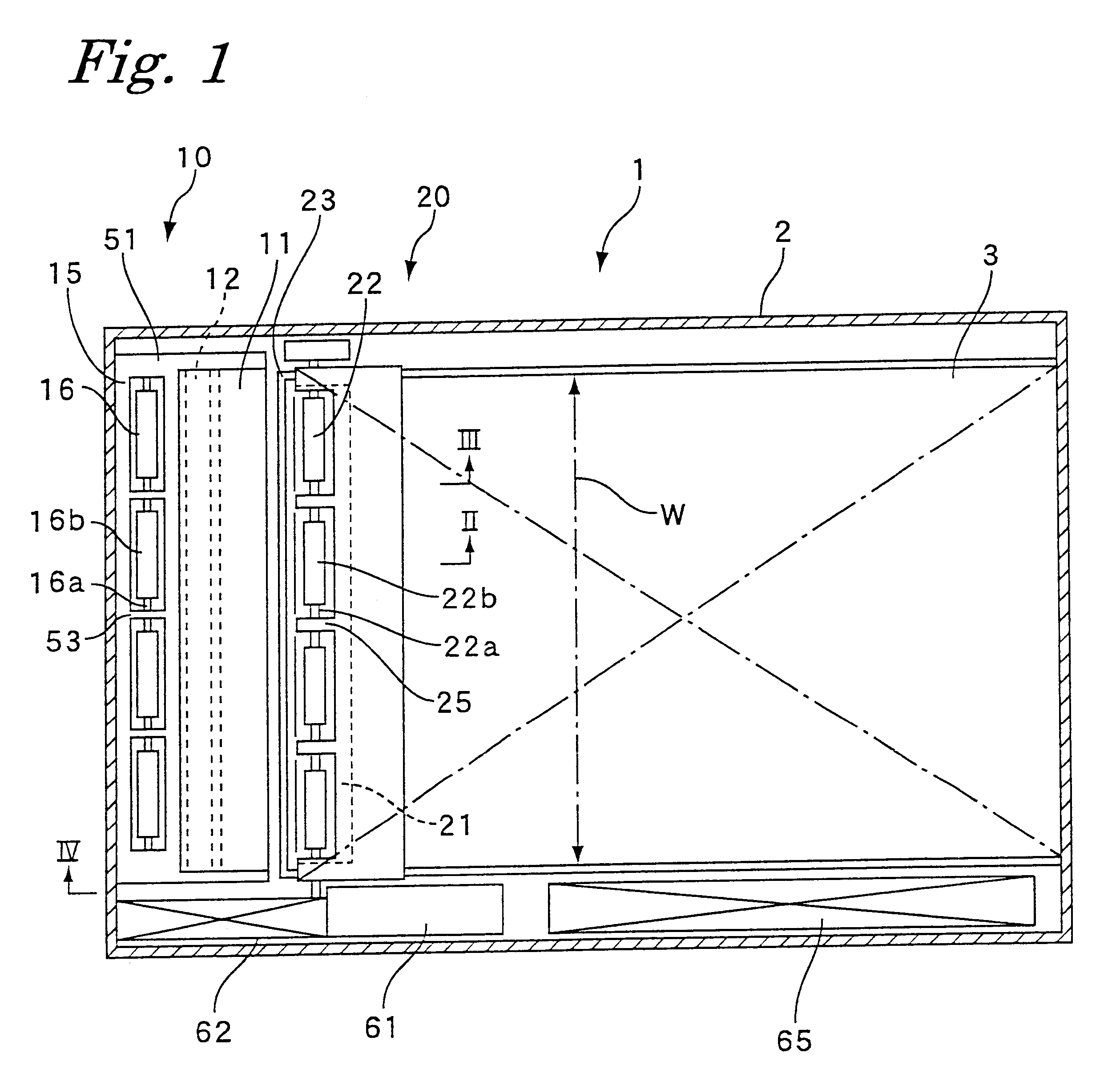
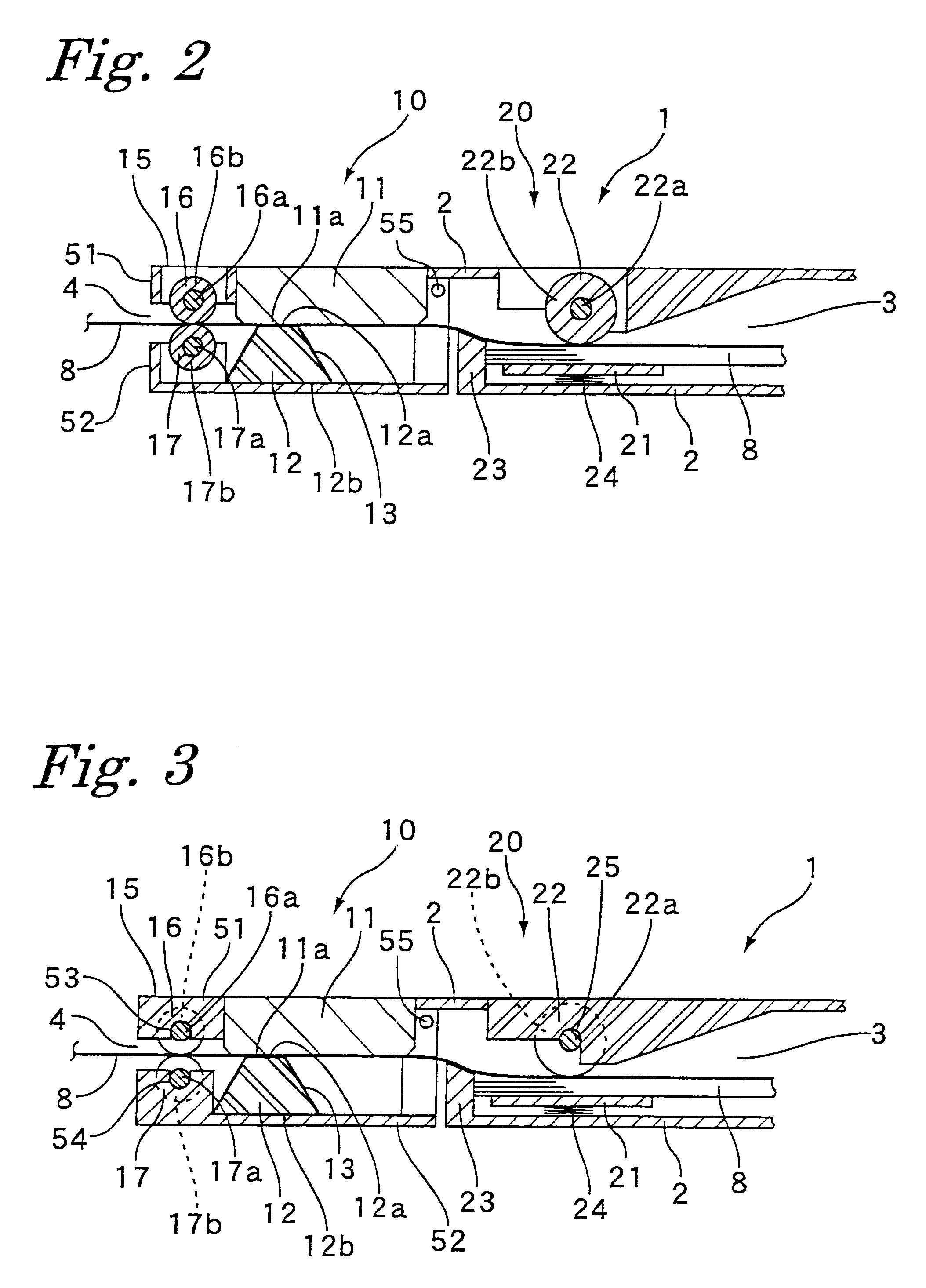
Description of an embodiment of the present invention will be given with reference to accompanying drawings. FIG. 1 shows a plane construction of a printer 1 according to the present invention. In addition, FIG. 2 and FIG. 3 show a section of a printing mechanism (printer assembly) 10 and a paper feed mechanism 20 of the printer 1 on an enlarged scale. The printer 1 of this embodiment is in an overall rectangular shape of A7 size (74 mm.times.105 mm), and is a portable type printer housed in a housing 2 having a thickness of about 5 mm, which is like a thin card as a whole. Within the housing 2, a space 3 for accommodating a thermal (thermosensible) type cut sheet of an A8 size (52 mm.times.74 mm) is provided, and from this accommodation space 3, a cut sheet 8 is supplied to the printer assembly 10 one by one by means of a paper feed mechanism 20, and a printed paper is output from a paper ejection port 4 on the opposite side.

As shown in FIG. 2 and FIG. 3, the paper feed mechanism 2...


PUM


Abstract

The printer and the printer assembly of the present invention has a line thermal head extending in the paper width direction; a non-roller type platen disposed so as to face the line thermal head for printing a thermal paper between the line thermal head and the platen; and a paper extracting device disposed on the paper ejection side of the line thermal head and the platen for feeding a thermal paper between a first and a second roller. The non-roller type platen can press the thermal paper with uniform pressure and without distortion even if it is thin. Moreover, it is possible to prevent distortion of the rollers of the extracting device even with small diameters by supporting middle parts of each shaft of respective rollers. Therefore, a thin and compact printer assemblies and printers are provided.

Description

1. Field of the InventionThe present invention relates to a printer assembly and a printer for printing on a thermal paper of sheet.2. Description of the Related ArtComputers are used for many applications, and along with the development of them, various types of printer are required as a peripheral device for output. Conventionally, when the computer was large and could not be moved, printers were large for having a fast processing speed. On the contrary, as personal computers such as a desktop type or the like become popular, printers become small, and desktop size printers have become popular.Recently, various types of computers have been developed and used. Portable type computers are also developed such as a notebook type to a portable or mobile type such as PDA, that has a size easily put in a pocket. Moreover, as the Internet becomes popular, applications of the computer are widespread in various fields such as information service and communication, and the variation of users...

Claims


Application Information

Patent Timeline
IPC IPC(8): B41J11/02B41J13/076B41J11/08B41J3/36
CPCB41J3/36B41J13/076B41J11/08
Inventor FUJIWARA, HITOSHI
Owner F&F
Why Eureka
Try Eureka