Irrigation positioning system

a positioning system and irrigation system technology, applied in the field of irrigation positioning system, can solve the problems of requiring expensive calibration at installation, errors in compass measurement, and system tolerances,

Inactive Publication Date: 2003-01-28
RAVEN INDUSTRIES INC
View PDF14 Cites 30 Cited by
  • Summary
  • Abstract
  • Description
  • Claims
  • Application Information

AI Technical Summary

Benefits of technology

The present invention provides an improved positioning system by using differential global positioning system ("DGPS") methods to monitor (or track) the absolute and / or relative position of a selected location on the conduit assembly referenced from the fixed, known position of a central tower. In one embodiment, a first global positioning system ("GPS") receiver mounted at the fixed tower generates differential correction information and provides this correction information via wire or otherwise to a second GPS receiver mounted at a selected location on the conduit assembly of the irrigation assembly.
In another more particular embodiment of the present invention, the positioning system is made up of two GPS receivers, the first of which is programmed to generate differential corrections and is installed at the center of a pivot irrigation assembly, where it does not move. The second GPS receiver is installed at or near the moving end of the pivot irrigation assembly and is connected by twisted shielded wire to the first GPS receiver. The second GPS receiver receives the differential corrections from the first GPS receiver over the wire and generates corrected GPS position information. The position information enters a microprocessor system where distance and bearing are computed, averaged and reported, e.g., once every 30 seconds, to a central, controller for the irrigation system.

Problems solved by technology

Unfortunately, however, errors in the magnetic compass can exceed the system tolerances because electric current used to drive the wheel motors can cause errors in compass measurements and require expensive calibration at installation.
Unfortunately, with this technique, the wheel location system can suffer from a build up of errors due to slippage and mud buildup causing an apparent wheel diameter error.

Method used


Image

  • Irrigation positioning system
  • Irrigation positioning system
  • Irrigation positioning system

Examples


Embodiment Construction

5.1 Overview

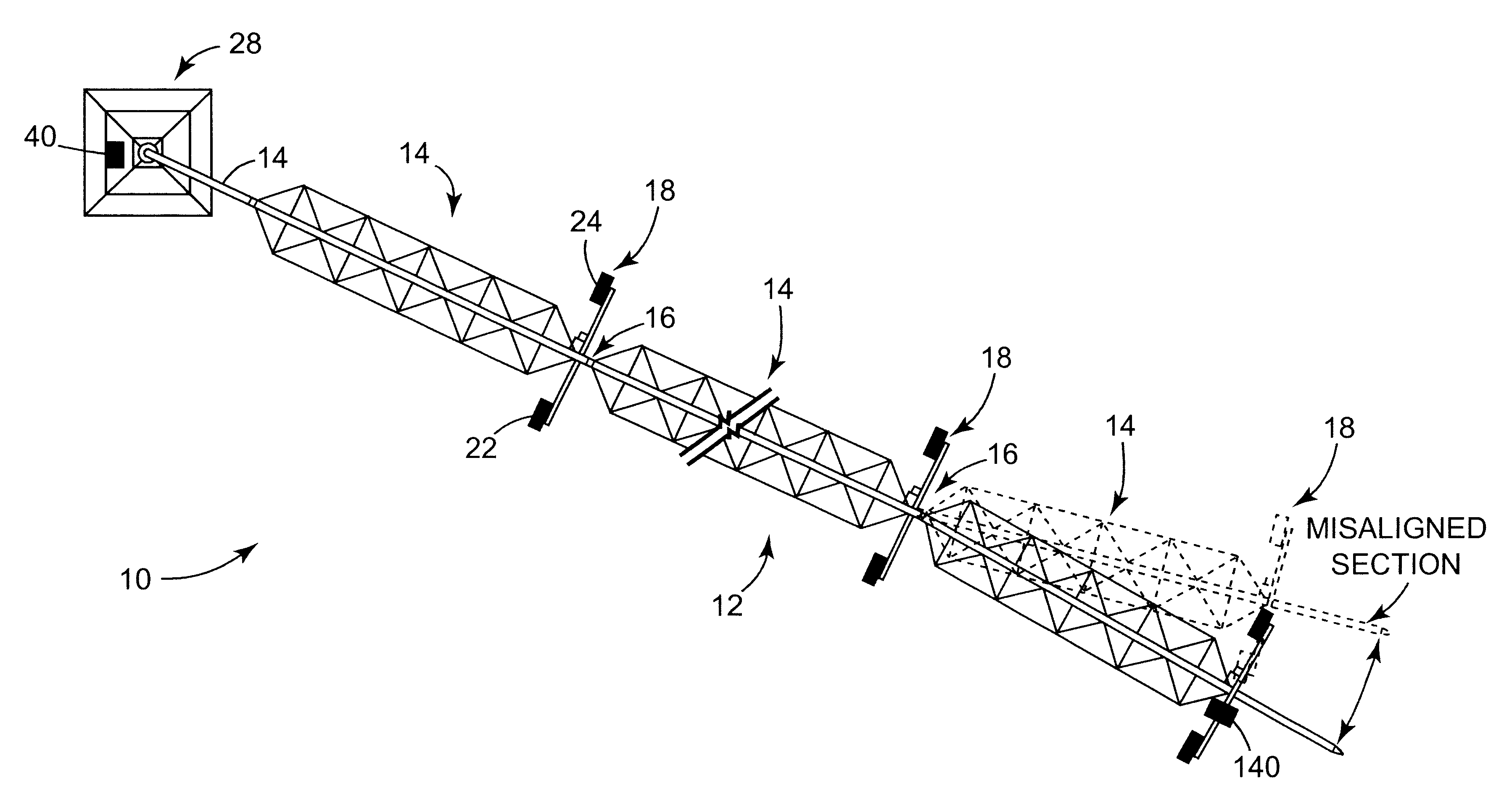
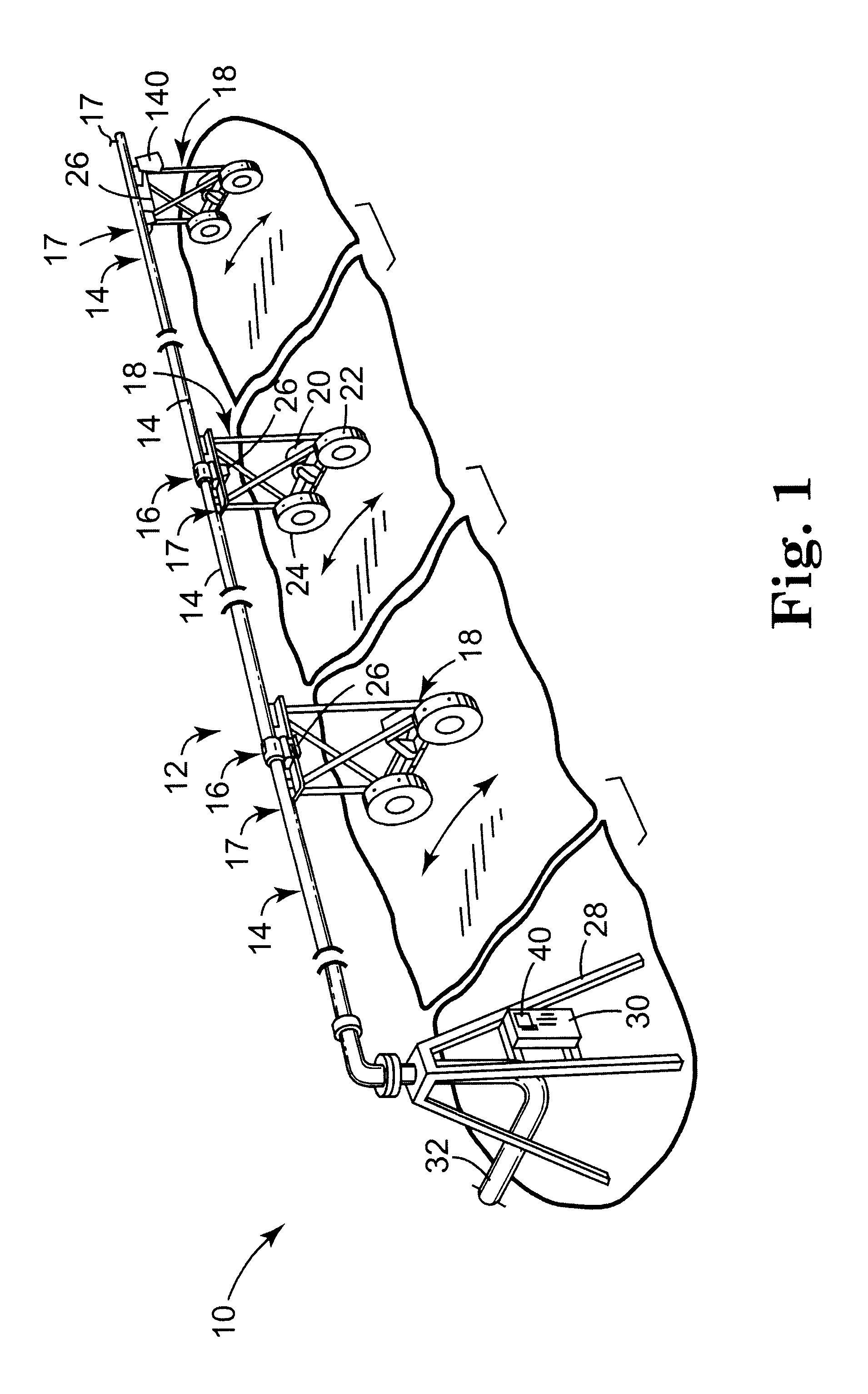
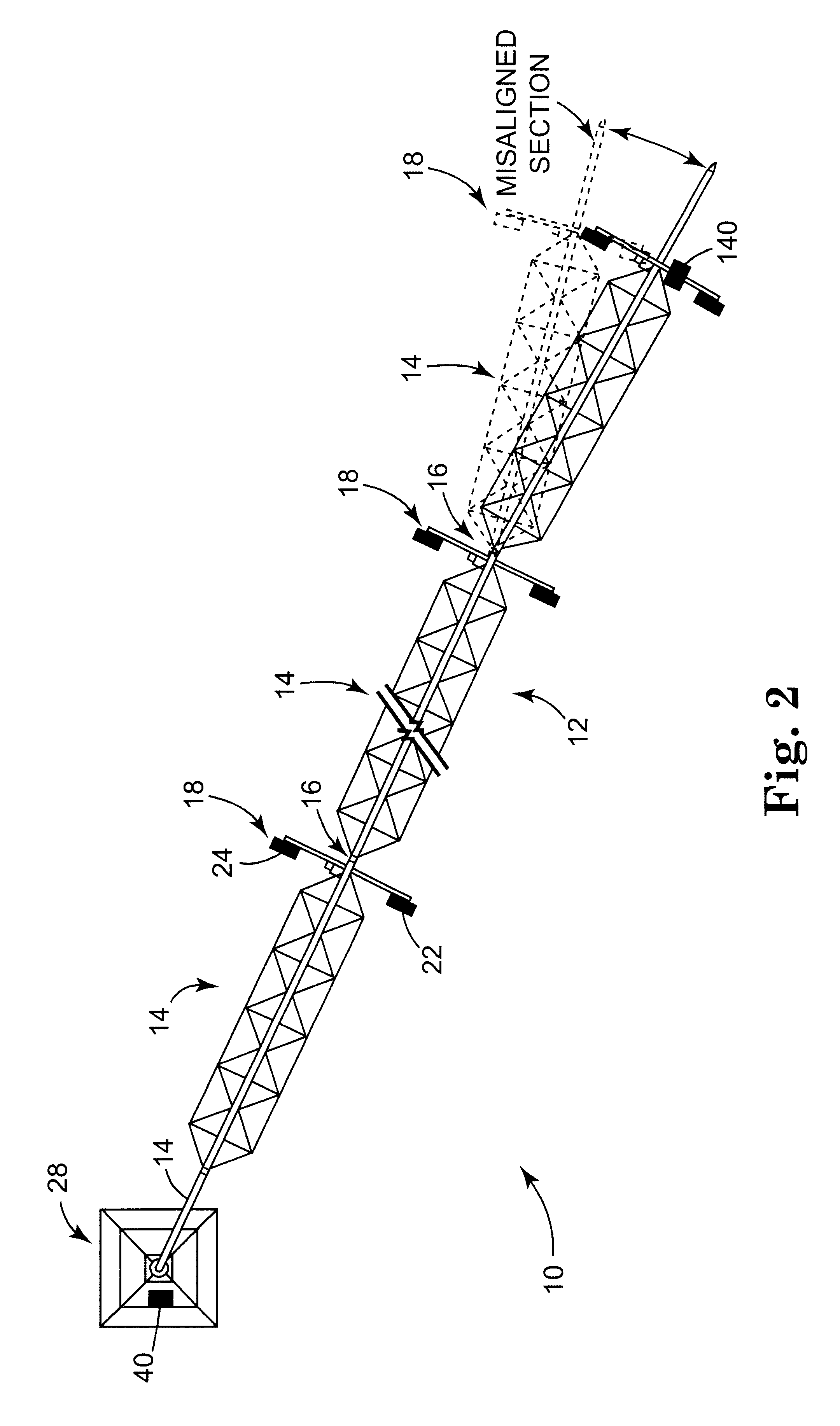
With reference to FIGS. 1 and 2, a center pivot type irrigation system 10 is shown. System 10 generally includes a conduit assembly 12 pivotally mounted to a central pivot tower 28. Conduit assembly 12 includes a plurality of conduit sections 14, which are pivotally jointed at adjacent ends by couplings 16, which are supported by self-propelled carriages 18. Conduit assembly 12 also includes spray heads 17 distributively mounted along conduit sections 14 for selectively applying water and chemical applications onto a field. Each carriage 18 includes a selectively and reversibly operable motor 20, which is drivingly attached to a pair of wheels 22, 24 for driving conduit assembly 12 about the central pivot tower 28. Each carriage 18 also includes carriage control module 26 for controlling motor 20.

The central pivot tower 28 typically includes a central control box 30 for providing power to the individual control modules 26. Central tower 28 also includes a water supply in...


PUM


Abstract

A means of accurately determining the position of a selected location such as at the end of a center-pivot irrigation system by using two Global Positioning System (GPS) receivers. The first GPS receiver is located at a fixed, known position such as at the center of the pivoting irrigation system while the second GPS receiver is located on a moving portion of the irrigation system. The first GPS receiver compares the GPS receiver reported position against the actual position and reports by wire or radio link the position differences to the second GPS, where the differences are used to remove errors from the second receiver's measured position.

Description

1. TECHNICAL FIELDThe present invention relates generally to positioning systems for automated irrigation systems. In particular, the present invention relates to an improved position sensing system in a center pivot irrigation system.2. BACKGROUNDKnowing (or being able to calculate) the position of each spray head along the conduit assembly of a center pivot irrigation ("CPI") system is important for the precision delivery of water, fertilizer, herbicides, and pesticides. In fact, systems that control the delivery of liquids along the length (or conduit assembly) of the CPI system can require an accuracy of 3 meters or better to be effective.Present methods of determining spray head positions such as by tracking the end of the conduit assembly include the, for example, the use of a flux-gate magnetic compass to derive angular bearing and by knowing the distance from the center to end allows the position at all points along the irrigation system to be known. Unfortunately, however, ...

Claims


Application Information

Patent Timeline
Patent Type & Authority Patents(United States)
IPC IPC(8): A01B79/00A01G25/09A01G25/00
CPCA01G25/092A01B79/005
Inventor FOWLER, CLARENCE W.POWELL, GERALD D.FOWLER, DAVID A.
Owner RAVEN INDUSTRIES INC
Why Eureka
Try Eureka