
Hand-held machine tool with dust extraction

a technology dust extraction, which is applied in the field of hand-held machine tools with dust extraction, can solve the problems of complex folding filter change, dust box that is unsuitable for self-supporting fastening, and the difficulty of emptying the dust box of the known hammer drill with relative difficulty

Inactive Publication Date: 2003-02-04
ROBERT BOSCH GMBH
View PDF9 Cites 160 Cited by
  • Summary
  • Abstract
  • Description
  • Claims
  • Application Information

AI Technical Summary

Benefits of technology

The power tool with dust removal according to the invention has the advantage over the prior art that a very lightweight and rugged dust box is produced which has a particularly large filter surface area with a high degree of air permeability and improved fine dust filtration. Furthermore, because the dust box has a number of covers, it can be emptied more easily and in a more environmentally sound manner than dust boxes with only one cover.
Since the at least one cover is coupled in drawer fashion to the side walls of the dust box, the dust box can be opened in a particularly gentle manner so that the dust cannot be undesirably agitated or spilled.
Since the dust box is embodied as a skeletal body and its walls are embodied as covers which close in a dustproof manner and can be used in a detachable fashion and the air escape openings also have a folded filter, the air permeability is further improved while dust filtration is assured, wherein filter surfaces can be arbitrarily cleaned or replaced independently of each other.
Since at least one of the covers is coupled to the dust box by means of hinges, it can be opened in a controlled, gentle manner similar to the drawer-like embodiment. This prevents an undesirable spilling of dust.
Since the filter lamellas of the folded filter are disposed lateral to the longitudinal axis of the dust box, the incoming dust-laden air can be influenced so that a relatively low amount of turbulence and therefore a high vacuum action on the work piece being machined is assured.
Since the surface of the dust box supporting the cover is inclined in relation to the incoming air in such a way that the dust box tapers in a wedge shape toward the machine, dust-minimized flow conditions are produced which further improve the dust removal.
Since one of the side walls or the bottom part of the dust box is transparent at least in some areas, the fill level of the dust box can be monitored optically in much the same way as with a viewing glass.
Since only the covers respectively have a filter, in particular a folded filter, and as the only part of the dust box with air openings, the filter surface area can be dimensioned as particularly large. As a result, there is only a slight buildup of dust-laden air and the efficiency of dust suction removal is high. In addition, starting at a particular layer thickness, the dust can as a result automatically detach from the folded filter and under the influence of gravity, can fall into the dust box, from which it can easily be emptied.
Since the surface of the dust box supporting the cover is inclined in relation to the incoming air in such a way that the dust box tapers in a wedge shape toward the machine, dust-minimized flow conditions are produced which further improve the dust removal.
Since the cover is elastically affixed to the dust box in a sealed fashion, it is particularly easy to open and can easily be reclosed securely.
Since the folded filter is disposed in cover-like parts of the dust box, it is particularly easy to replace due to the fact that it is either newly glued in place or the entire cover with the filter is replaced.
Since the dust box can be fastened to the power tool with detent locking means, it can be detached, emptied, and refastened in a particularly easy, reliable, time-saving manner.
Since the inlet fitting of the dust box can be closed by means of a valve, an undesirable escape of dust can be effectively prevented when the dust box is detached from the power tool.

Problems solved by technology

The dust box of the known hammer drill can only be emptied with relative difficulty, and changing the folded filter is complicated.
Furthermore, this dust box is unsuitable to be fastened in a self-supporting way to power tools with integrated dust suction for blow injecting the dust.
These plastic cassettes have a tendency to permit fine dust to pass through, have a tendency to clog up, and are difficult to empty and clean.

Method used


Image

  • Hand-held machine tool with dust extraction
  • Hand-held machine tool with dust extraction
  • Hand-held machine tool with dust extraction

Examples


Embodiment Construction

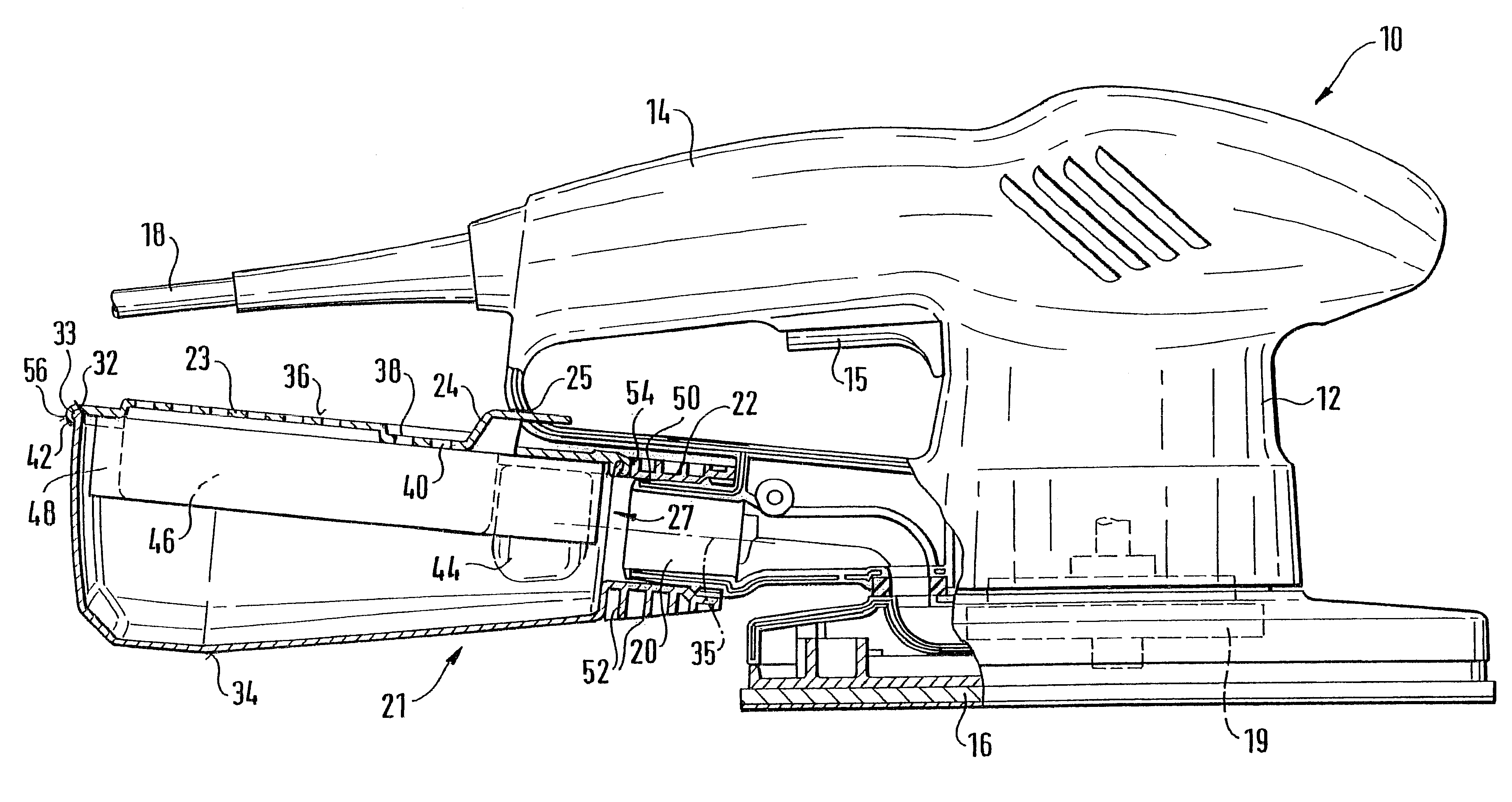
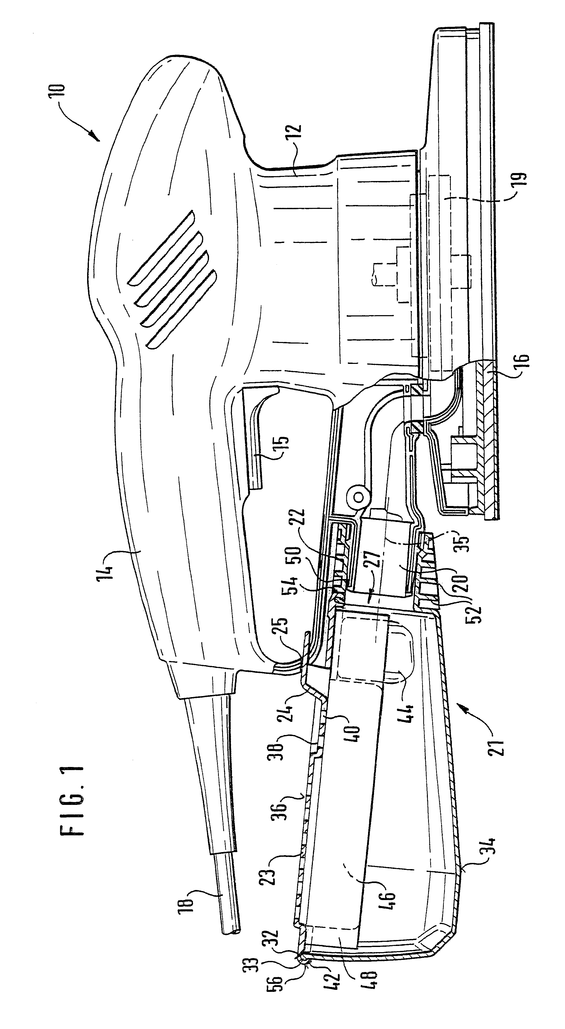
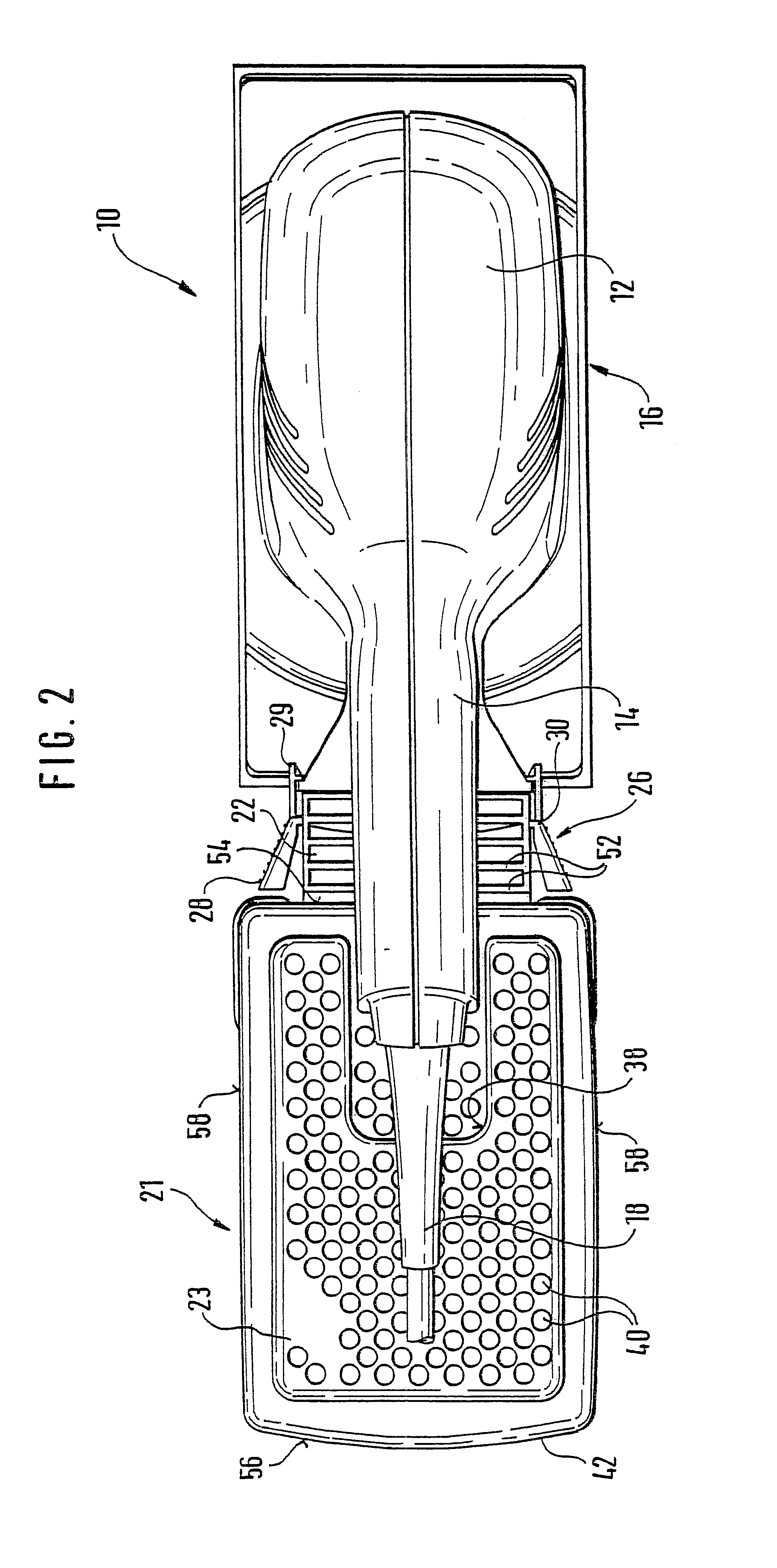
FIG. 1 shows the longitudinal section through a power tool 10 embodied as an orbital sander with a housing 12, which has a handle 14 with a switch 15, the underside of which has a tool 16 movably fastened to it, which is embodied as a sanding plate with through openings. At the bottom end of the handle 14, the power tool 10 has an electric power cable 18 and inside the housing 12, it has a fan propeller 19. When the power tool is operated, this fan propeller 19 generates a vacuum above the sanding plate 16 and between the sanding plate 16 and a work piece. As a result, when the power tool 10 is operated, sanding dust is sucked through the through openings of the sanding plate 16 and is blown through an ejection fitting 20 of the housing 12 and into a dust box 21 via its injection fitting 22.

The ejection fitting 20 supports the injection fitting 22 of the dimensionally rigid, self-supporting dust box 21. This dust box is air tight--except for the injection opening 27 of the injection...


PUM


Abstract

A power tool (10) having a dust suction device (19) integrated into its housing (12) and having an ejection fitting (20) which is connected to the dust suction device (19) and can be detachably fastened with its injection fitting (22) to a dustproof dust box (21) is particularly suitable for containing sanding dust because of a number of side walls (34) of the dust box (21) have air openings (40) and on the inside, support at least one filter element (48), in particular a folded filter, which overlaps the air openings (40).

Description

PRIOR ARTThe invention is based on a power tool having a dust suction device integrated into its housing.U.S. Pat. No. 5,467,835 has disclosed a hammer drill with a dust box and a fan attached to it which can suck drilling dust produced into the dust box. The suction air generated by the fan enters a suction conduit in the vicinity of the tool and is conveyed via this conduit into the dust box. In the box, the suction air passes through a dust filter embodied as a folded filter which separates out the drilling dust that collects in the dust box. The dust box has a bottom that pivots up for the removal of the folded filter and for the emptying of the drilling dust and is disposed together with the fan in a common housing that can be connected to the hammer drill by means of a relatively complex coupling.The dust box of the known hammer drill can only be emptied with relative difficulty, and changing the folded filter is complicated. Furthermore, this dust box is unsuitable to be fast...

Claims


Application Information

Patent Timeline
Patent Type & Authority Patents(United States)
IPC IPC(8): B23Q11/00B24B55/00B24B55/10B24B23/00
CPCB24B55/10B23Q11/0046
Inventor REICH, DORISWUENSCH, STEFFEN
Owner ROBERT BOSCH GMBH
Learn More