Method and apparatus for shielding electromagnetic emissions from an integrated circuit

a technology of integrated circuits and electromagnetic emissions, which is applied in the direction of semiconductor devices, semiconductor/solid-state device details, cooling/ventilation/heating modifications, etc., can solve the problems of em emissions that can leak from the chassis into the surrounding environment, and can conceivably generate electronic noise in neighboring devices,

Inactive Publication Date: 2003-02-04
INNOVATIVE FOUNDRY TECH LLC
View PDF29 Cites 28 Cited by
  • Summary
  • Abstract
  • Description
  • Claims
  • Application Information

AI Technical Summary

Problems solved by technology

Once the EM emissions radiate into the open area of a computing system's chassis, it can be very difficult to contain.
The EM emissions can leak from the chassis into the surrounding environment.
These emissions can therefore cause a variety of significant problems when the ICs are employed in computing system.
The emissions can conceivably generate electronic noise in neighboring devices that interfere with their operation.
Also, the Federal Communications Commission ("FCC") regulates the amount of EM emissions from a variety of commercially sold products, and emissions from an IC, e.g., the proces

Method used


Image

  • Method and apparatus for shielding electromagnetic emissions from an integrated circuit
  • Method and apparatus for shielding electromagnetic emissions from an integrated circuit
  • Method and apparatus for shielding electromagnetic emissions from an integrated circuit

Examples


Embodiment Construction

)

Illustrative embodiments of the invention are described below. In the interest of clarity, not all features of an actual implementation are described in this specification. It will of course be appreciated that in the development of any such actual embodiment, numerous implementation-specific decisions must be made to achieve the developers' specific goals, such as compliance with system-related and business-related constraints, which will vary from one implementation to another. Moreover, it will be appreciated that such a development effort, even if complex and time-consuming, would be a routine undertaking for those of ordinary skill in the art having the benefit of this disclosure.

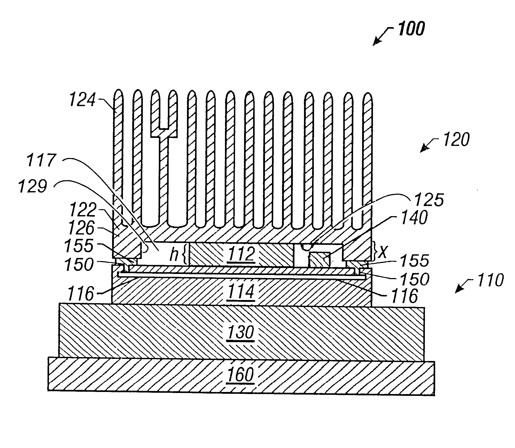
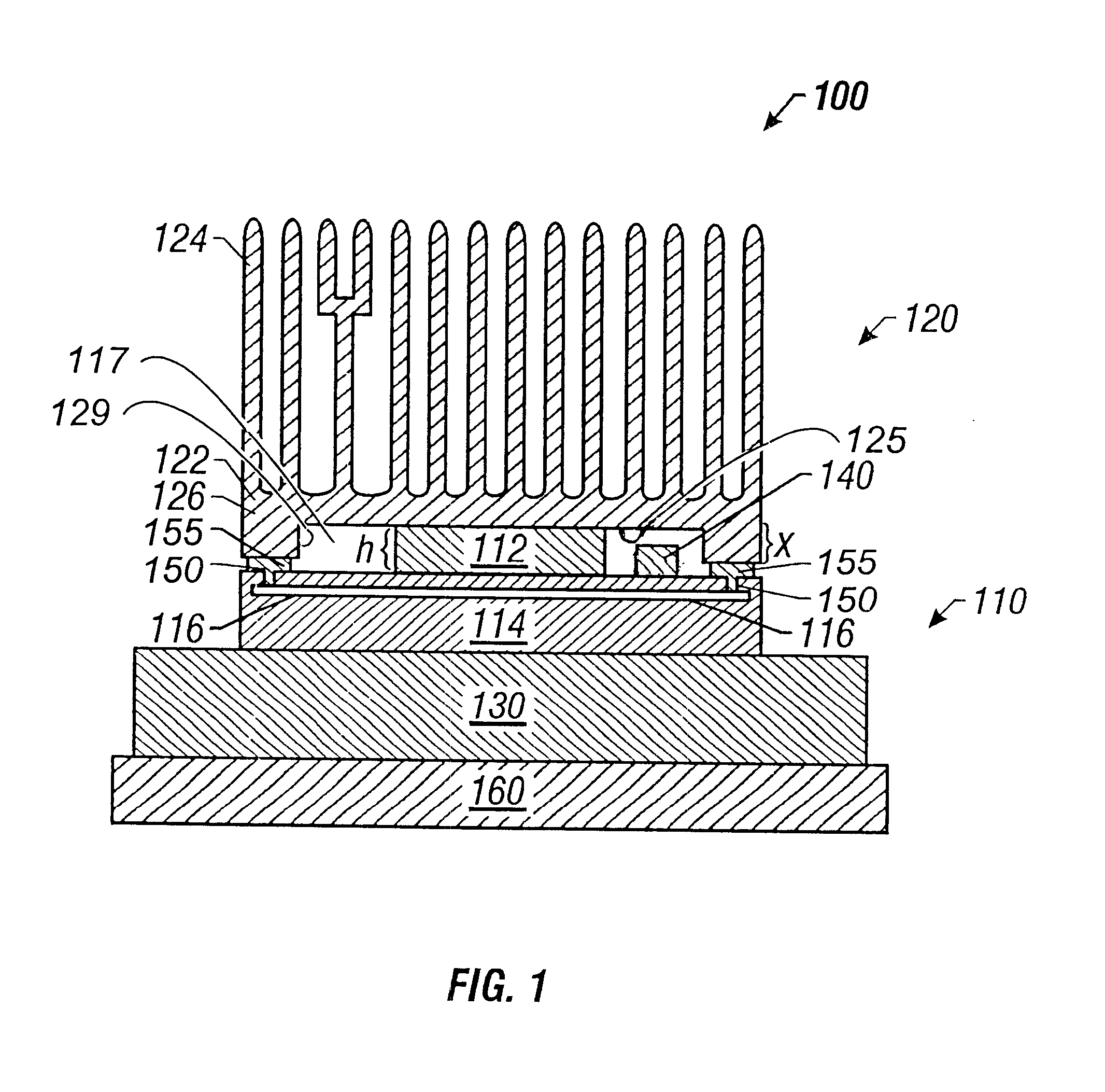
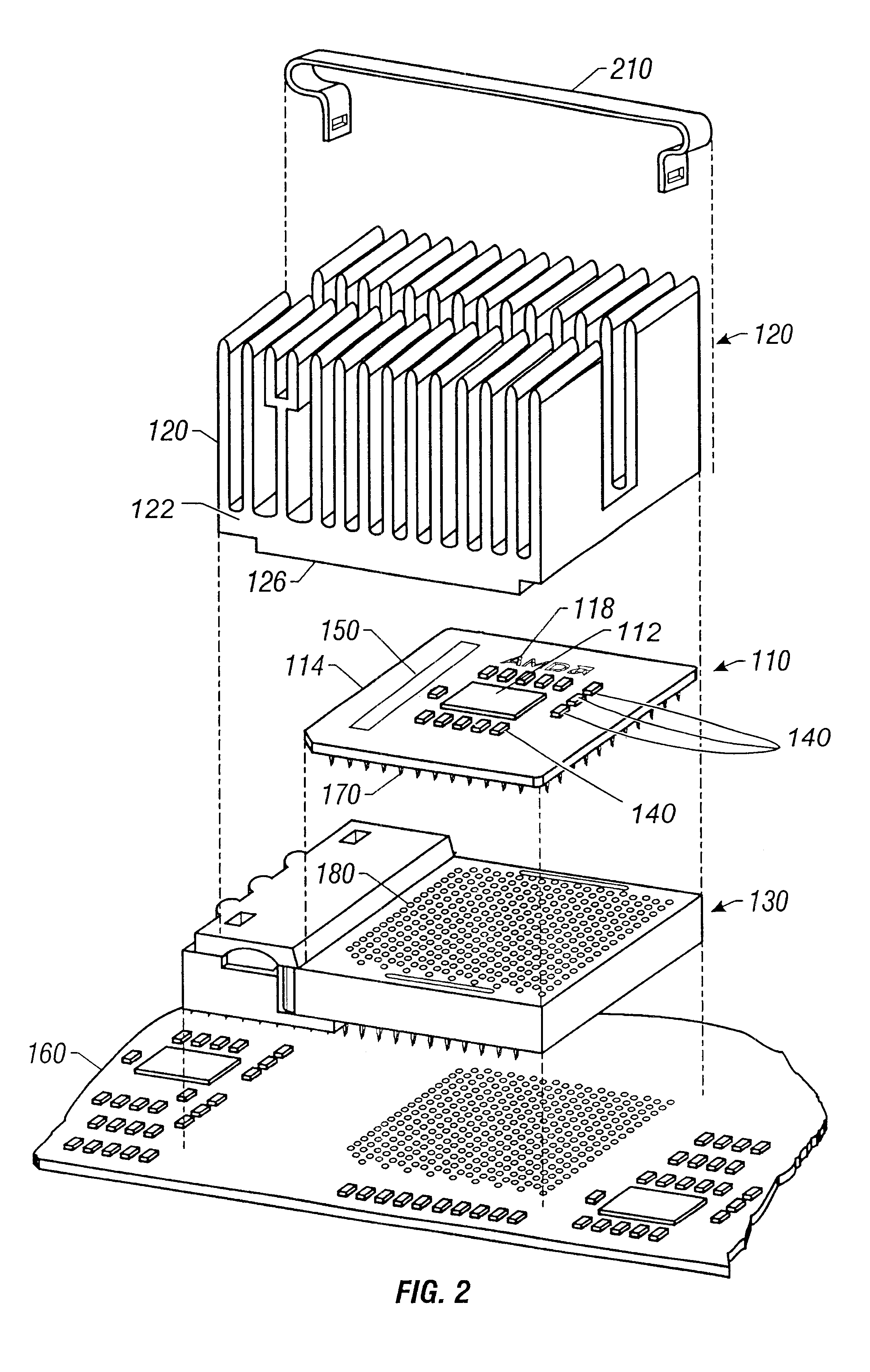
Turning now to the drawings, FIG. 1 and FIG. 2 depict one particular embodiment of an apparatus 100 constructed in accordance with the present invention. FIG. 2 is an exploded, isometric view of the apparatus 100 of FIG. 1. The apparatus 100 comprises packaged IC 110 on which a heatsink 120 is mounted...


PUM


Abstract

A conductive plane of an integrated circuit package and a heatsink combine to form a structure for controlling electromagnetic emissions from the integrated circuit die that is mounted in the package. The heatsink includes a base and a projecting portion extending from the base. The projecting portion is electrically connected to an exposed ground plane in the package. The projecting portion defines a recess positioned over the integrated circuit die, which thermally engages the integrated circuit die.

Description

1. Field of the InventionThe present invention pertains to the control of electromagnetic emissions from an electronic device and, more particularly, from an integrated circuit device.2. Description of the Related ArtAn integrated circuit ("IC") can emit or radiate electromagnetic ("EM") waves directly from the die on which the actual circuits are formed. Once the EM emissions radiate into the open area of a computing system's chassis, it can be very difficult to contain. The EM emissions can leak from the chassis into the surrounding environment. These emissions can therefore cause a variety of significant problems when the ICs are employed in computing system. The emissions can conceivably generate electronic noise in neighboring devices that interfere with their operation. Also, the Federal Communications Commission ("FCC") regulates the amount of EM emissions from a variety of commercially sold products, and emissions from an IC, e.g., the processor of a computing system, can ca...

Claims


Application Information

Patent Timeline
IPC IPC(8): H01L23/34H01L23/552H01L23/40
CPCH01L23/4093H01L23/552H01L2924/16152
Inventor ANDRIC, ANTHONY M.HILL, RUEL
Owner INNOVATIVE FOUNDRY TECH LLC
Why Eureka
Try Eureka