System and method for mounting x-ray tube in CT scanner

a technology of computer tomography and mounting system, which is applied in the field of radiography, can solve the problems of time-consuming, costly, and time-consuming process of calibrating the position of the x-ray tube on the ct scanner, and achieve the effect of convenient removal or replacement of the heavy and cumbersome x-ray tube by the person

Inactive Publication Date: 2003-02-11
ANLOGIC CORP (US)
View PDF11 Cites 60 Cited by
  • Summary
  • Abstract
  • Description
  • Claims
  • Application Information

AI Technical Summary

Benefits of technology

The system is designed to make lifting and handling the heavy and cumbersome x-ray tube easier for a person removing or replacing the x-ray tube in a CT scanner. According to one aspect, the system further includes elongated guides adapted to connect to ends of the rods and guide the rods into the channels of the tracks. According to another aspect, the rods are adjustable with respect to the tracks in a direction parallel to the z-axis of the scanner, such that the position of a focal spot of the x-ray tube can be adjusted along the z-axis. According to an additional aspect, the rods are adjustable with respect to the x-ray tube in a direction generally parallel to an x-axis of the scanner, such that the position of the focal spot can be adjusted along the x-axis. According to a further aspect, the rods are adjustable with respect to the x-ray tube in a direction generally parallel to a y-axis of the scanner, such that the position of the focal spot can be adjusted along the y-axis.

Problems solved by technology

The process of calibrating the position of the x-ray tube on the CT scanner is time consuming, e.g., two to four hours to complete, and costly.
While Dobbs et al. provides a solution for pre-calibrating an x-ray tube prior to mounting the tube in a CT scanner, there still remains the problem of actually mounting the x-ray tube in a scanner.
As is known, CT scanners are relatively large structures (the gantry can be about six feet in diameter for example), and an x-ray tube is relatively heavy and bulky (an x-ray tube can weight two hundred pounds or more, for example).
An x-ray tube, therefore, can be awkward for one, or even two service people to handle, lift and mount in a CT scanner.

Method used


Image

  • System and method for mounting x-ray tube in CT scanner
  • System and method for mounting x-ray tube in CT scanner
  • System and method for mounting x-ray tube in CT scanner

Examples


Embodiment Construction

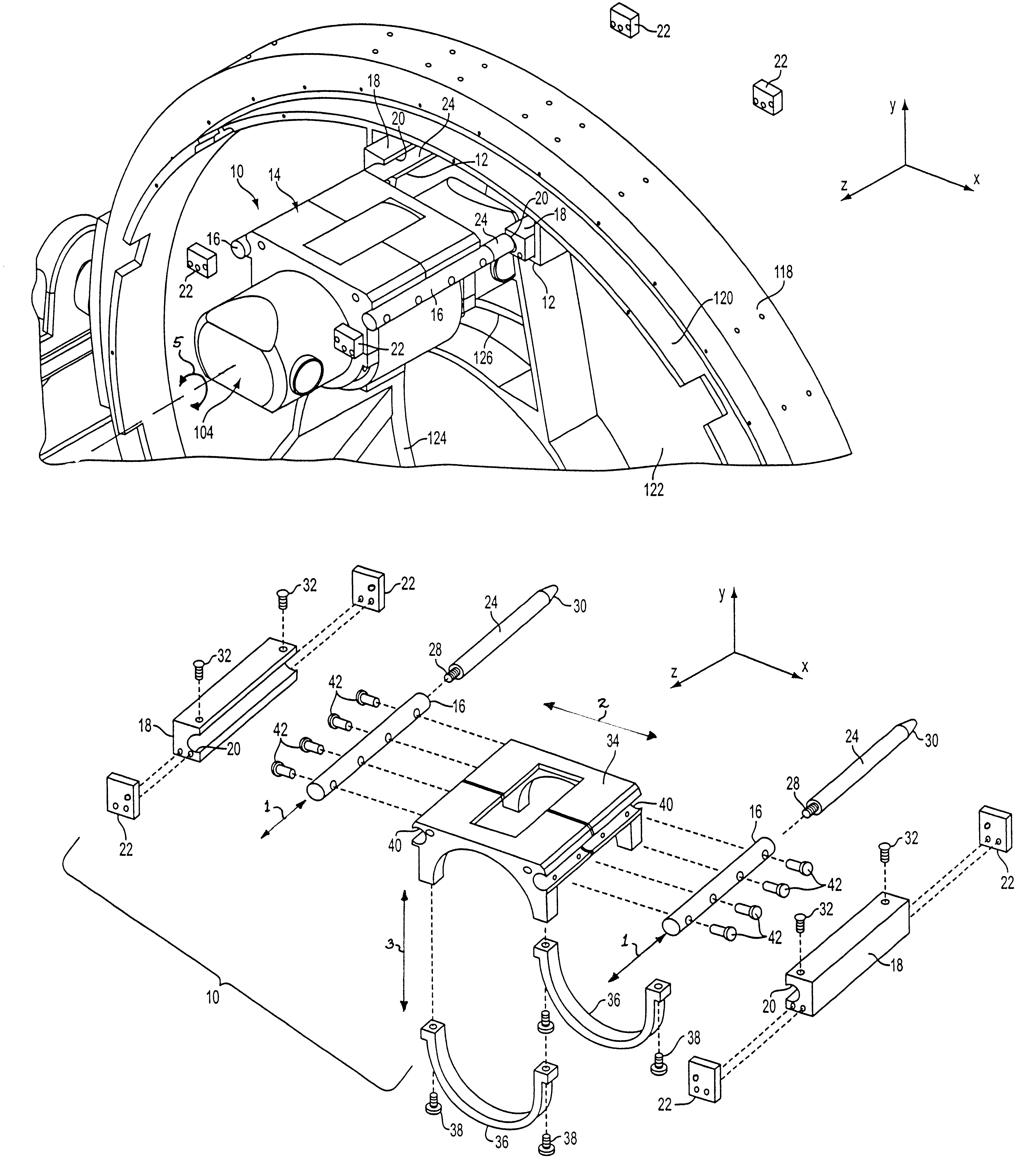
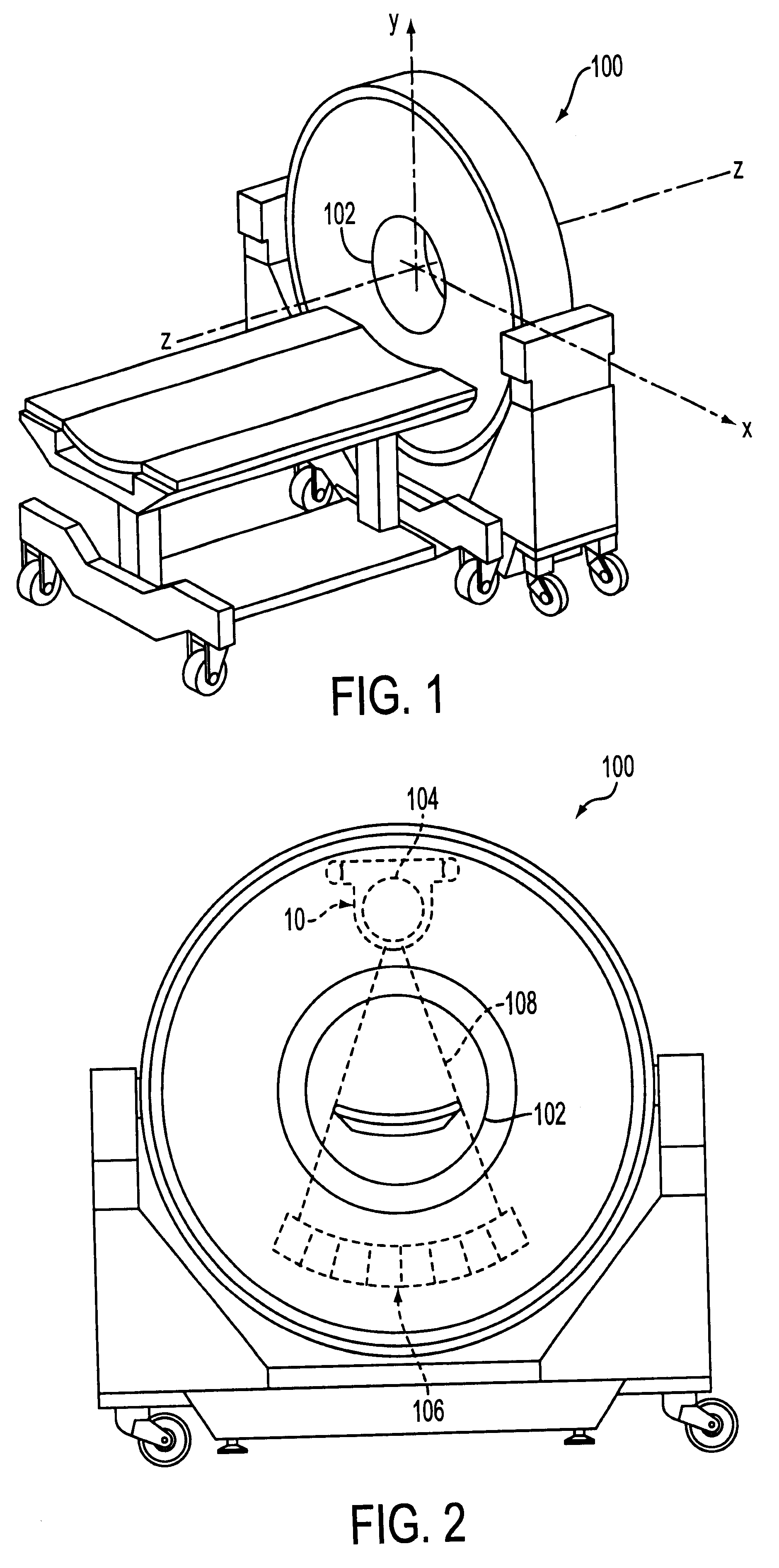
Referring first to FIGS. 1 and 2, in computed tomography, a patient (not shown) to be examined is positioned in a scan circle 102 of a computer tomography (CT) scanner 100, parallel with a z-axis of the scanner, and between an x-ray source, or tube 104 and a rectangular detector array 106. The x-ray tube 104 then projects a beam of energy, or x-rays 108, along a scan plane defined by an x-axis and a y-axis of the scanner 100, through the patient, to the detector array 106. By rotating the x-ray source about the z-axis and relative to the patient, radiation is projected through the patient from many different directions. An image of the scanned portion of the patient then is constructed by a computer from data provided by the detector array 106.

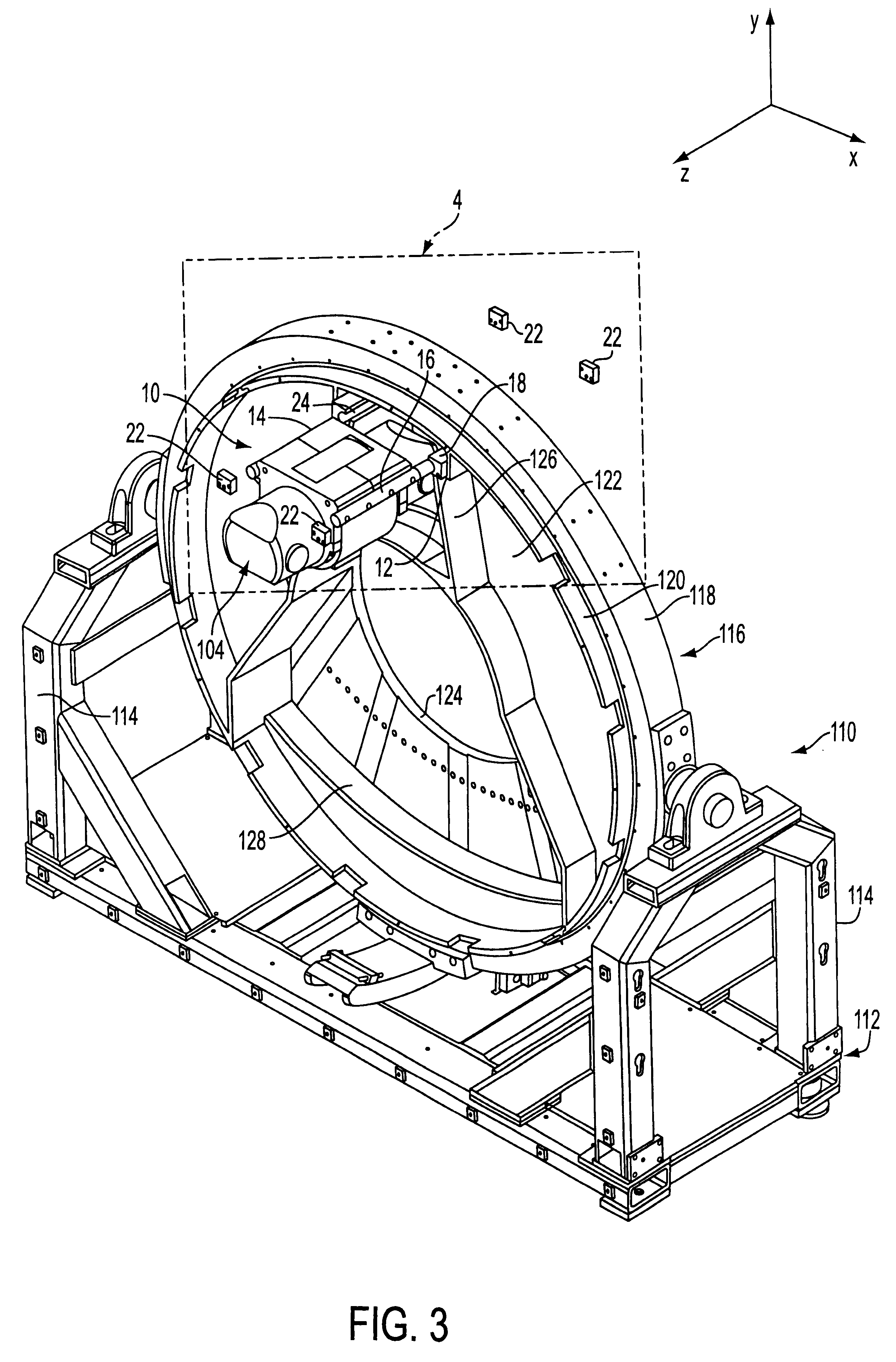
The CT scanner 100 of FIGS. 1 and 2 employs an x-ray tube mounting system 10 constructed in accordance with the present disclosure. The x-ray tube mounting system 10 is shown in greater detail in FIGS. 3 through 5, wherein like reference chara...


PUM


Abstract

The present disclosure provides a system for mounting an x-ray tube to a gantry disk of a CT scanner. The system is designed to make lifting and handling a heavy and cumbersome x-ray tube easier for a person removing or replacing the x-ray tube in a CT scanner. The system includes a harness adapted to be secured to the x-ray tube, at least two elongated rods secured to the harness, and two elongated tracks adapted to be secured to the gantry disk such that the tracks extend generally parallel with a z-axis of the CT scanner. Each track includes a channel for slidingly receiving one of the rods. The present disclosure also provides a method of mounting an x-ray tube in a gantry of a CT scanner. The method includes securing a harness to the x-ray tube, securing elongated rods to the harness such that the rods extend parallel to an axis of the x-ray tube, attaching elongated guides to ends of the rods, inserting distal ends of the guides into channels of elongated tracks in the gantry of the x-ray scanner, and sliding the guides and the rods into the channels of the tracks. Then the guides are removed from the rods, and stops are secured to ends of the tracks to retain the rods within the channels.

Description

FIELD OF DISCLOSUREThe present disclosure relates to the field of radiography and, in particular, relates to computer tomography ("CT") scanners. Even more particularly, the present disclosure relates to a system and method for mounting an x-ray tube within a CT scanner.BACKGROUND OF DISCLOSUREA typical CT scanner includes a gantry comprising an annular frame for rotatably supporting an annular disk about a rotation, or z-axis of the scanner. The disk includes a central opening large enough to receive a patient upon whom a scan is performed. An x-ray tube is positioned on one side of the disk diametrically across the central opening from an array of x-ray detectors. As the disk rotates, the x-ray tube projects a beam of energy, or x-rays, along a scan plane defined by an x-axis and a y-axis of the scanner, through the patient, to the detector array. By rotating the x-ray source about the z-axis and relative to the patient, radiation is projected through the patient from many differe...

Claims


Application Information

Patent Timeline
Patent Type & Authority Patents(United States)
IPC IPC(8): A61B6/03H05G1/00H05G1/02
CPCH05G1/02A61B6/035
Inventor TYBINKOWSKI, ANDREW P.SWAIN, RONALD E.DUFFY, MICHAEL J.NEMIROVSKY, LIDIA
Owner ANLOGIC CORP (US)
Why Eureka
Try Eureka