Process and apparatus for liquid delivery into a chemical vapor deposition chamber

a chemical vapor deposition chamber and liquid delivery technology, applied in chemical vapor deposition coating, combustion-air/fuel-air treatment, steam generation using steam absorption, etc., to prevent any internal condensation

Inactive Publication Date: 2003-02-18
AIXTRON AG
View PDF13 Cites 32 Cited by
  • Summary
  • Abstract
  • Description
  • Claims
  • Application Information

AI Technical Summary

Benefits of technology

The object of the invention is to achieve an improved evaporation apparatus enabling optimum volatilisation of the liquid pr

Problems solved by technology

When the liquid flows in the channels, it comes i

Method used


Image

  • Process and apparatus for liquid delivery into a chemical vapor deposition chamber
  • Process and apparatus for liquid delivery into a chemical vapor deposition chamber
  • Process and apparatus for liquid delivery into a chemical vapor deposition chamber

Examples


Embodiment Construction

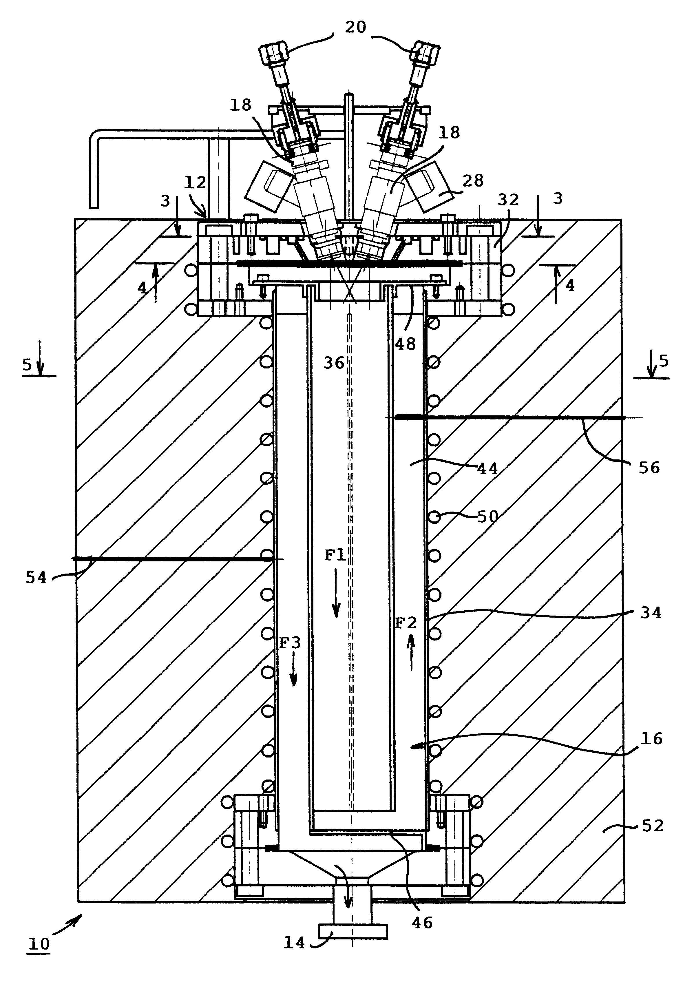
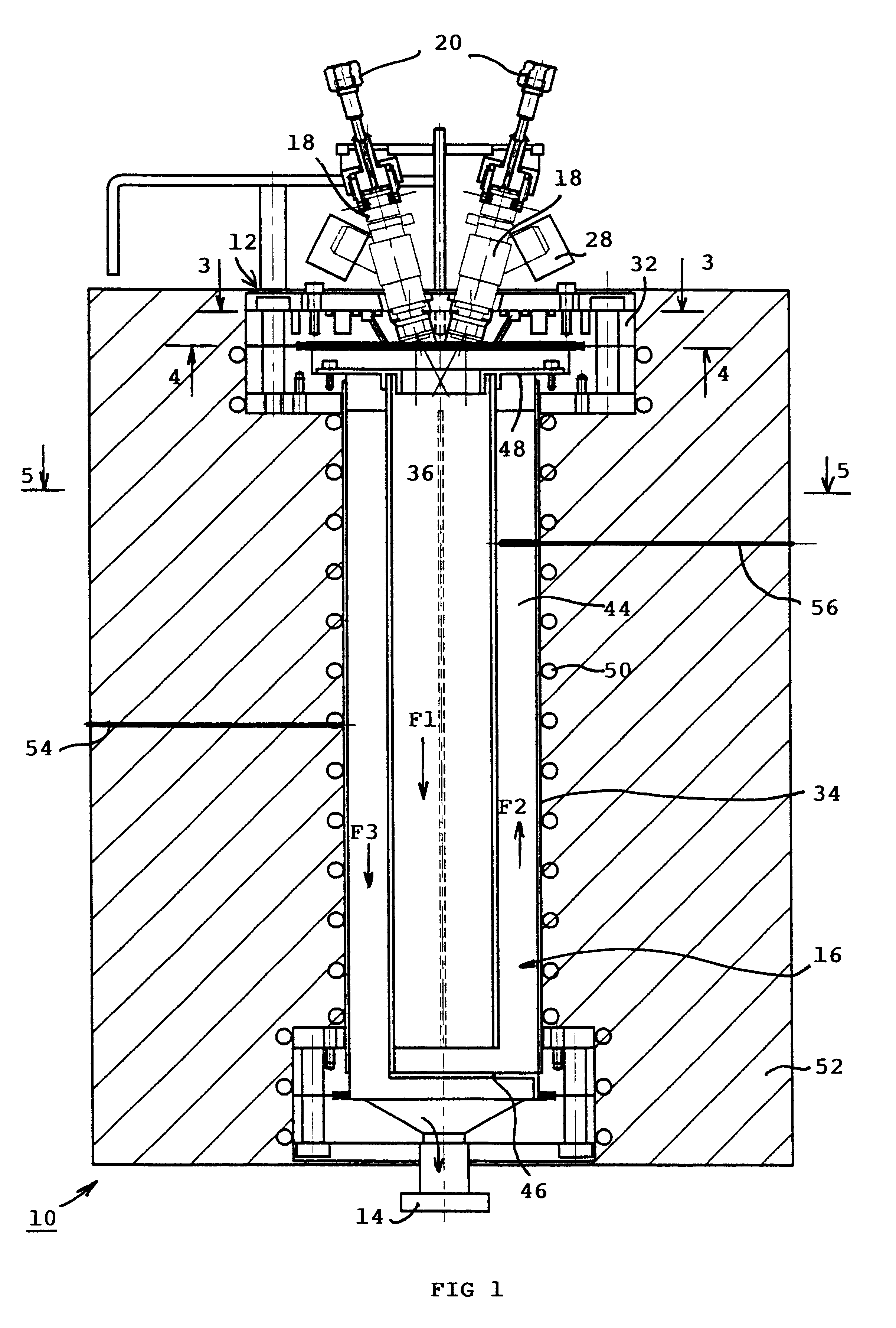
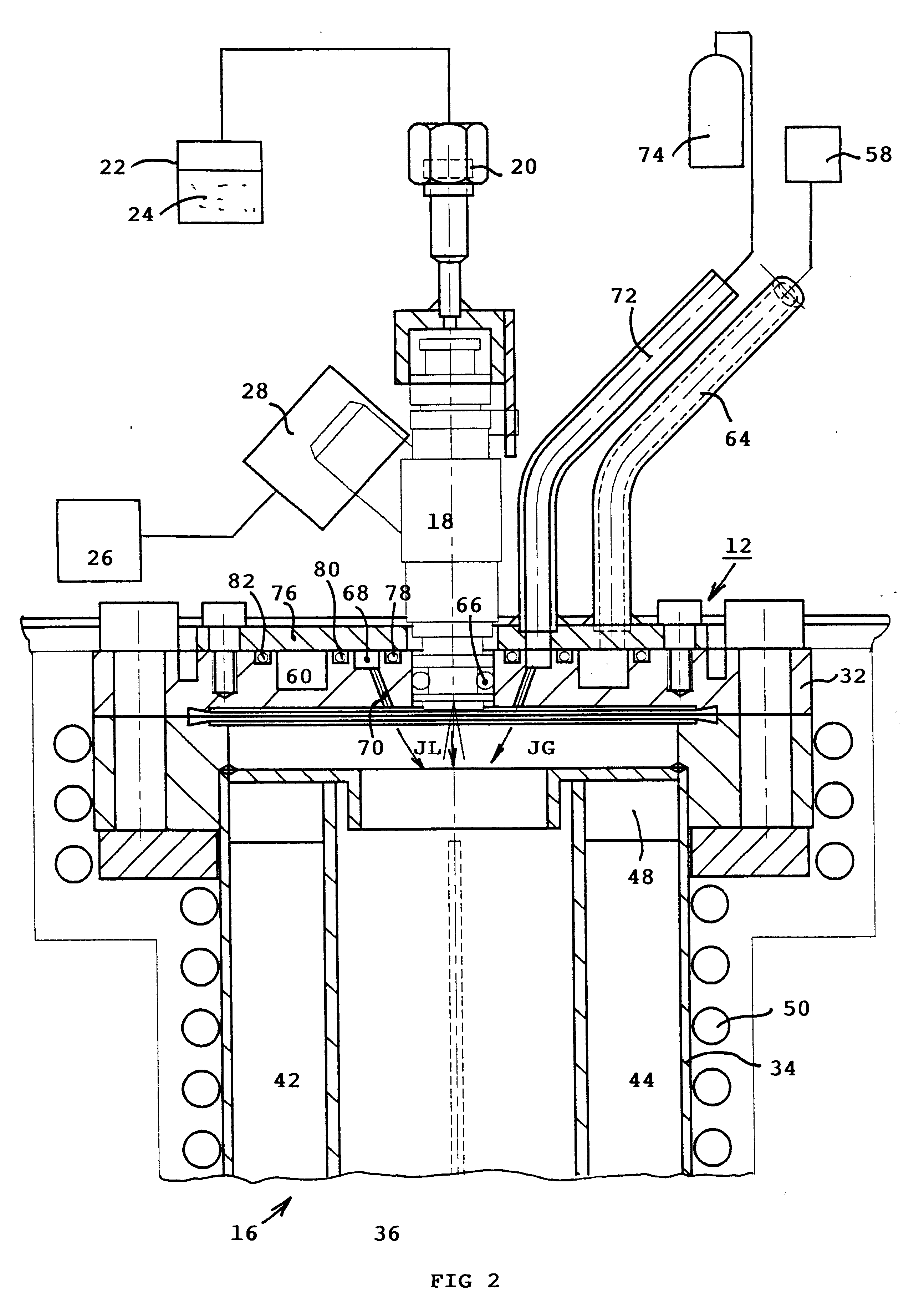
With reference to FIGS. 1 to 5, an evaporator apparatus 10 for liquid delivery of thin layers into a chemical vapour deposition CVD chamber comprises an inlet head 12 connected to an outlet tube 14 via an evaporation chamber 16 in a vacuum or at atmospheric pressure.

The inlet head 12 is equipped with at least one injector 18 having an inlet 20 connected to an external tank 22 filled with liquid precursors 24 or precursors in solution. The pressure in the tank 22 is greater than that present in the evaporation chamber 16, and each injector 18 periodically sends predetermined quantities of liquid 24 into the evaporation chamber 16, in which the liquid / vapour state change takes place. The injector 18 is formed by an electrovalve controlled on opening and closing by a microprocessor-based control circuit 26 connected to a connector 28 of the electrovalve. The injected liquid can be a pure liquid or a mixture of solvent and solute. The volume of liquid injected is perfectly controlled by...


PUM

PropertyMeasurementUnit
Timeaaaaaaaaaa
Temperatureaaaaaaaaaa
Flow rateaaaaaaaaaa

Abstract

An apparatus for liquid delivery of a chemical vapour deposition CVD installation comprises an inlet head equipped with at least one injector having an inlet for delivery of liquid precursors or precursors in solution. A vector gas injection circuit is rendered active simultaneously with injection of the liquid, the vector gas being directed to the vicinity of the injector after being heated. Each injector is cooled individually by water or coolant flow. The evaporation chamber comprises heating resistances for the change of liquid/vapor state of the precursors, and deviation means arranged so that the distance covered by the droplets and vapours of the precursors is greater than the distance in a straight line between the nozzle of the injector and the outlet tube.

Description

The invention relates to an apparatus for liquid delivery, in particular into a chemical vapour deposition CVD installation, or into a chemical vapour reaction reactor, comprising:an inlet head equipped at least with one injector or spray nozzle having an inlet for delivery of liquid precursors or precursors in solution,a control circuit to periodically inject droplets of preset volume of the liquid precursors or a continuous or pulsed aerosol flow into an evaporation chamber,injection means for injecting a vector gas into said evaporation chamber,heating means designed to heat the evaporation chamber to achieve the change of liquid / vapour state of the liquid precursors, or of the solvent and precursor mixture,and an outlet tube designed to send the vaporised injected precursors to a reactor.The CVD reactor is generally equipped with a pumping system or with a vent to create a vapour flow to the reactor.STATE OF THE TECHNIQUEThe document FR-A-2,707,671 describes a process and appara...

Claims


Application Information

Patent Timeline
IPC IPC(8): B01D1/00C23C16/448H01L21/205
CPCB01D1/0017C23C16/4486C23C16/4481
Inventor BRUTTI, THIERRYPIERRET, BENOITGUILLON, HERVE
Owner AIXTRON AG
Why Eureka
Try Eureka