Crankcase of internal combustion engine
A crankcase and internal combustion engine technology, applied in the direction of internal combustion piston engine, combustion engine, engine cooling, etc., can solve problems such as complex structure, and achieve the effects of preventing dew condensation, improving prevention, and preventing temperature drop.
- Summary
- Abstract
- Description
- Claims
- Application Information
AI Technical Summary
Problems solved by technology
Method used
Image
Examples
Embodiment Construction
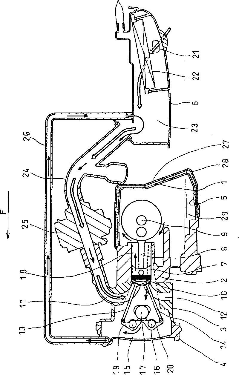
[0041] figure 1 is a sectional view showing main parts of a wet sump lubrication type 4-stroke internal combustion engine equivalent to the first embodiment of the present invention from the left side, with arrow F pointing forward of the internal combustion engine. figure 1Among them, the internal combustion engine is composed of a crankcase 1, a cylinder 2 integrally formed with the crankcase 1, a cylinder head 3, a cover 4, an oil pan 5 and an air cleaner 6 at the bottom of the crankcase. Piston 7 is slidably housed in cylinder 2 and connected to crankshaft 9 via connecting rod 8 .
[0042] The combustion chamber 10 is arranged on the side of the piston 7 in the cylinder head 3 . An intake port 11 and an exhaust port 12 are provided on the cylinder head 3 and have their respective inner ends open to the combustion chamber 10 . At the respective inner end openings of the intake port 11 and the exhaust port 12, an intake valve 13 and an exhaust valve 14 for opening and cl...
PUM
 Abstract
Description
Claims
Application Information
 - R&D
- Intellectual Property
- Life Sciences
- Materials
- Tech Scout
- Unparalleled Data Quality
- Higher Quality Content
- 60% Fewer Hallucinations
Browse by: Latest US Patents, China's latest patents, Technical Efficacy Thesaurus, Application Domain, Technology Topic, Popular Technical Reports.
© 2025 PatSnap. All rights reserved.Legal|Privacy policy|Modern Slavery Act Transparency Statement|Sitemap|About US| Contact US: help@patsnap.com


