Crankcase of internal combustion engine

A technology of crankcase and internal combustion engine, applied in the direction of internal combustion piston engine, combustion engine, engine cooling, etc., can solve problems such as complex structure, and achieve the effect of preventing dew condensation, improving rigidity, and improving prevention.

Inactive Publication Date: 2008-01-02
HONDA MOTOR CO LTD
View PDF4 Cites 5 Cited by
  • Summary
  • Abstract
  • Description
  • Claims
  • Application Information

AI Technical Summary

Problems solved by technology

[0006] In the related art, since the cooling water is introduced into the heating channel and heated there to heat the cooling water, a heater needs to be provided and the structure is complicated

Method used


Image

  • Crankcase of internal combustion engine
  • Crankcase of internal combustion engine
  • Crankcase of internal combustion engine

Examples


Embodiment Construction

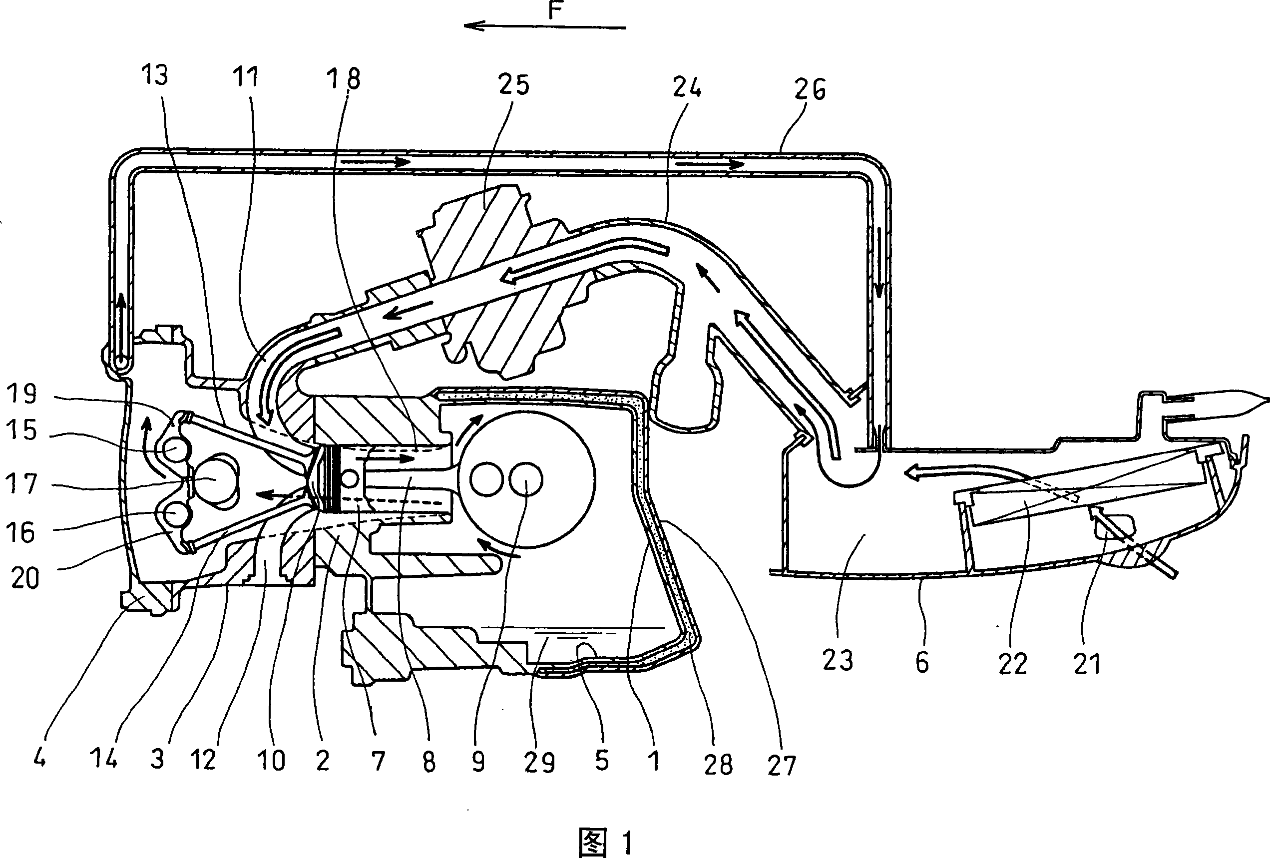
[0041] 1 is a sectional view showing the main part of a wet sump lubrication type 4-stroke internal combustion engine equivalent to the first embodiment of the present invention from the left side, with arrow F pointing forward of the internal combustion engine. In Fig. 1, an internal combustion engine is composed of a crankcase 1, a cylinder 2 integrated with the crankcase 1, a cylinder head 3, a cover 4, an oil pan 5 and an air cleaner 6 at the bottom of the crankcase. Piston 7 is slidably housed in cylinder 2 and connected to crankshaft 9 via connecting rod 8 .

[0042]The combustion chamber 10 is arranged on the side of the piston 7 in the cylinder head 3 . An intake port 11 and an exhaust port 12 are provided on the cylinder head 3 and have their respective inner ends open to the combustion chamber 10 . At the respective inner end openings of the intake port 11 and the exhaust port 12, an intake valve 13 and an exhaust valve 14 for opening and closing the respective open...


PUM


Abstract

To prevent dew condensation in a crankcase in a lower part of the crankcase, wherein an oil pan is an integral part of an internal combustion engine, to prevent lubricating oil from being diluted. A crankcase cover covers at least an oil pan out of a crankcase and is provided to the bottom of the crankcase. A heat insulating material is provided between the crankcase and the crankcase cover. A cooling fluid passage for providing a circulation to cool a cylinder or a cylinder head is provided between the crankcase and the crankcase cover. A passage at least one end of which reaches a cylinder head from a crankcase via a cylinder block forms at least a part of a blowby gas passage, is directly provided to the crankcase, the cylinder block and the cylinder head. A flow control valve is arranged in the cylinder block or the cylinder head.

Description

[0001] Cross References to Related Applications [0002] Based on 35 USC 119, this application claims priority from Japanese Patent Applications No. 2006-108402 filed April 11, 2006 and No. 2006-143305 filed May 23, 2006, the entire contents of which are hereby incorporated by reference incorporated. technical field [0003] The invention relates to a structure of a crankcase for an internal combustion engine. More specifically, it relates to a structure for preventing dew condensation in a crankcase and preventing lubricating oil from being diluted due to inflow of the condensed dew. In addition, the present invention also relates to a crankcase emission control system for an internal combustion engine, wherein a flow control valve allowing only flow to the side of the intake system is provided on a blowby gas (blowby gas: or blowby gas) passage, the blowby The air passage connects the intake system, including the intake port provided to the cylinder head, to the crankcase....

Claims


Application Information

Patent Timeline
Patent Type & Authority Applications(China)
IPC IPC(8): F01M5/00F01P3/20
CPCY02T10/146
Inventor 五十岚和则小笠原诚
Owner HONDA MOTOR CO LTD
Why Eureka
Try Eureka