
Telecommunications service delivery

a technology for telecommunications and services, applied in the field of telecommunications service delivery, can solve the problems of low bandwidth of radio frequency channels and substantial amount of signalling generated in the network

Inactive Publication Date: 2003-02-18
BRITISH TELECOMM PLC
View PDF8 Cites 85 Cited by
  • Summary
  • Abstract
  • Description
  • Claims
  • Application Information

AI Technical Summary

Benefits of technology

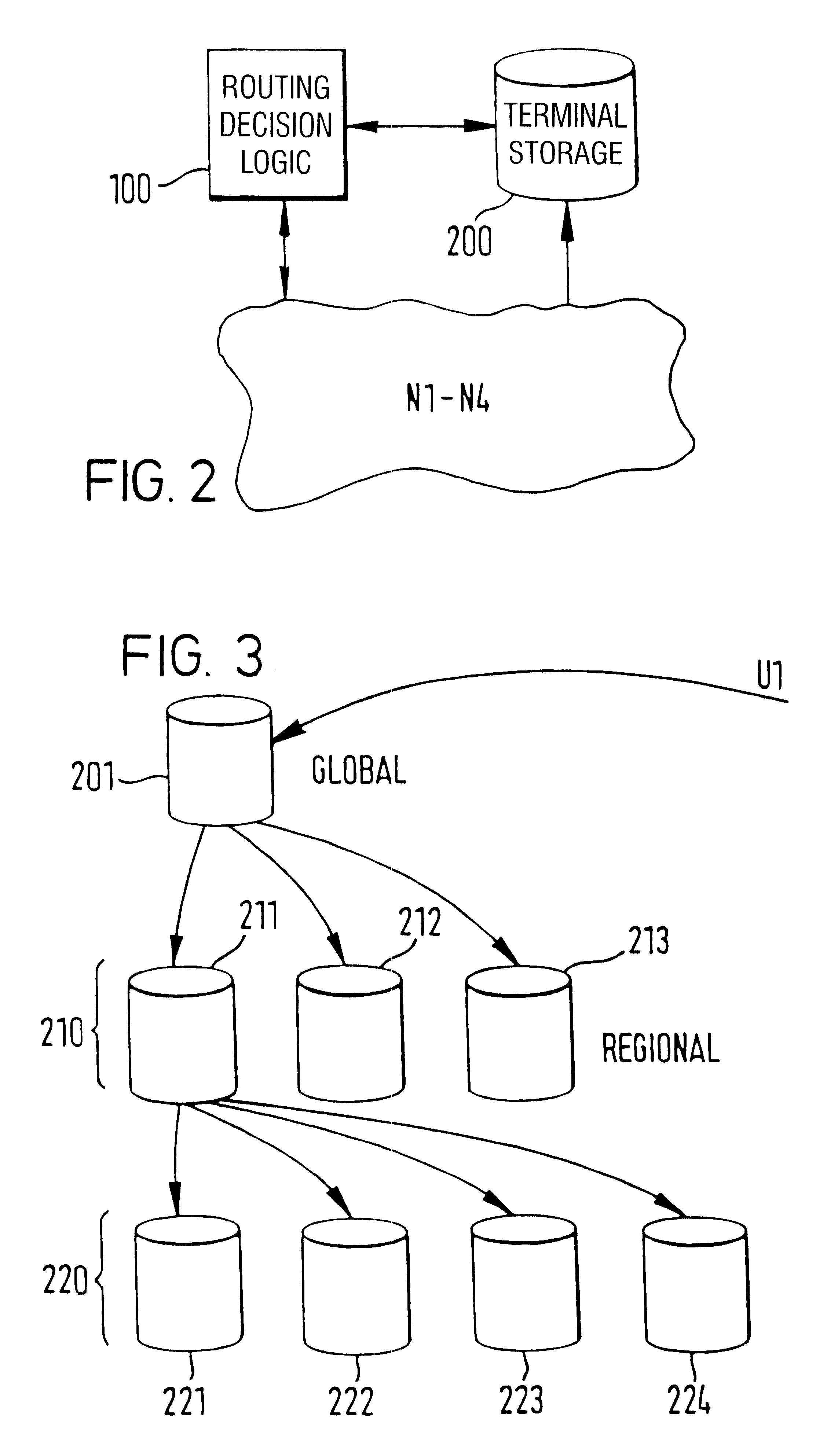
Furthermore, in a preferred embodiment, multiple passes may be employed corresponding to successive layers of a hierarchical organisation of bidding entities, those entities in the middle layers acting as resource suppliers to entities in layers above them and as resource purchasers to entities in layers below them. This enables further increases in the size of the network without vastly increasing the volume of signalling traffic across the network, particularly if (as preferred) the entities in each layer are geographically distributed.
It may at this point be mentioned that in so-called `Computer-Telephony Integration` (CTI), it has been proposed to group a computer and a telephone on the same desktop together; to note when a particular user logs onto the computer, and to route all that user's telephone calls to the telephone with which the computer shares a desktop, thus effectively tying together a particular telephone and a particular computer in a pair.

Problems solved by technology

However, radio frequency channels generally have available the lowest bandwidth due to demands on the RF spectrum and to the channel conditions within the RF spectrum.
Whilst this arrangement is suitable in many applications, as networks grow in size the amount of signalling generated within the network may be substantial.

Method used


Image

  • Telecommunications service delivery
  • Telecommunications service delivery
  • Telecommunications service delivery

Examples


Embodiment Construction

General Overview of Physical Layer

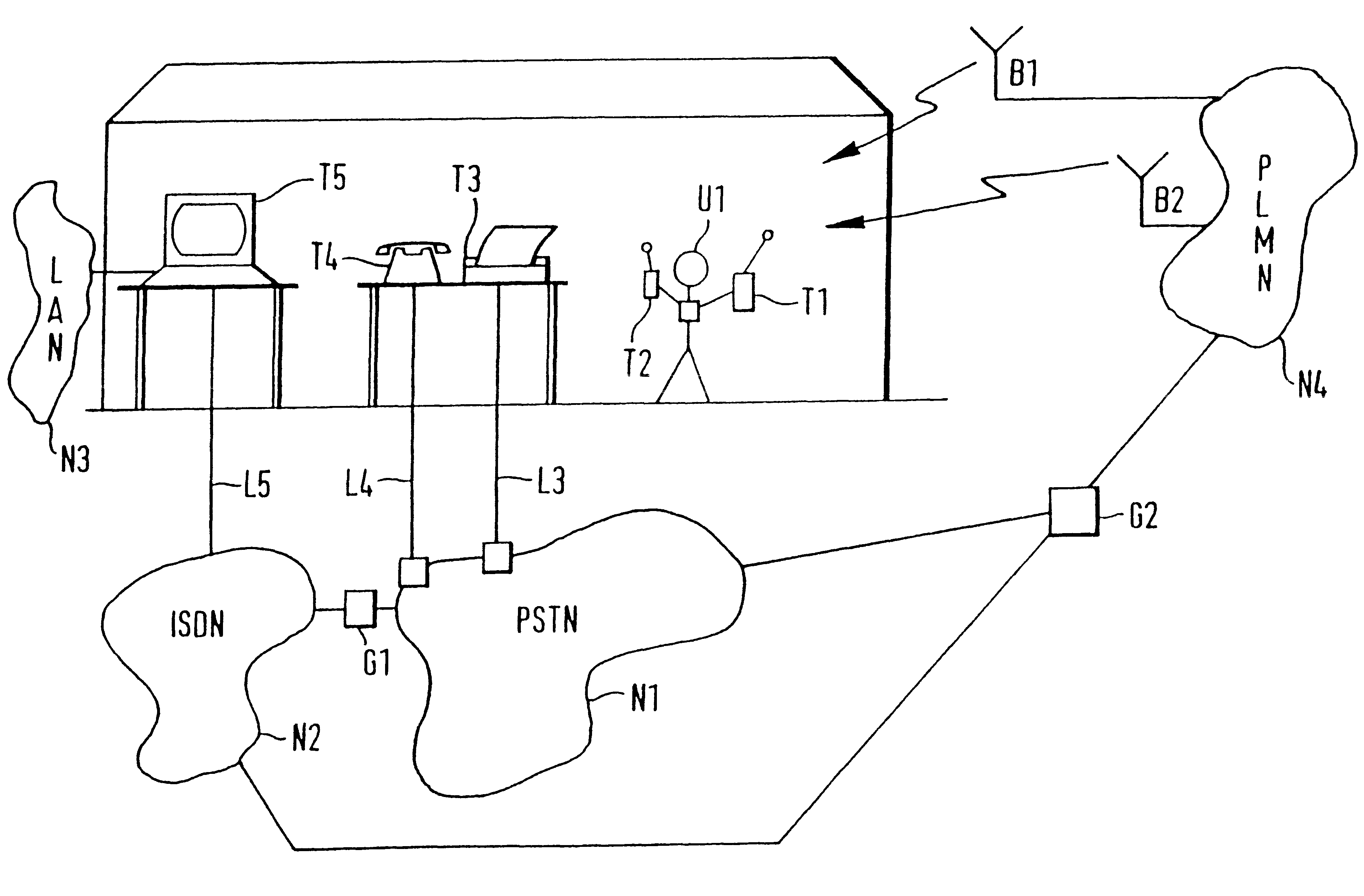
Referring to FIG. 1, at the physical or bearer level the telecommunications environment of a user U1 comprises a cellular telephone T1 and a personal digital assistant T2 carried by the user; a facsimile apparatus T3 and conventional telephone T4 at a desk a few feet from the user; and a computer workstation T5 including a modem at a desk top some meters away from the user, all within a single building.

The workstation T5 in this case comprises a local area network (LAN) server, connected to further terminals T6-T9 (not shown) at different distances from the user.

The various terminals T1-T9 are each capable of receiving different signal formats, as follows:

T1--voice or low bit rate data.

T2--low bit rate data (receive only).

T3--facsimile image signals.

T4--narrow bandwidth audio.

T5--high bit rate data in various formats.

In communication with the various terminals are a number of different communications channels forming parts of different notional netw...


PUM


Abstract

Routing apparatus for a telecommunication system includes a telecommunications user apparatus arranged to generate a request for a telecommunications delivery service, to receive a plurality of telecommunications delivery service offers and to select one of them. The system also intends a plurality of telecommunication service supply apparatuses each arranged to receive one of the request to generate an offer signal specifying a proposed delivery service and to receive an acceptance signal indicating acceptance thereof and, on receipt thereof, to generate a service provision invitation. The system further provides a plurality of resource supplier apparatuses each representing a communications resource arranged to communicate with each of said service supply apparatuses. The resource supplier apparatus is arranged to receive an invitation to determine whether the telecommunications resource they represent would contribute to the provision of the corresponding service; and, if so, to signal this to the service supply apparatus. The service supply apparatus is arranged, on the basis of signals from the resource supplier apparatus to select the route subsequent to the offer of the service.

Description

This invention relates to telecommunications apparatus and methods. More particularly, this invention relates to apparatus and methods for transmitting signals (specifically signals with information or a data content) in multiple different formats.RELATED ARTThe formats may simply be alternative technical representations of the same information; for example, different graphics formats. Alternatively, each format may be in a different medium; for example, image, text and audio formats. Further, the formats may represent something of the same information content but using different volumes of data; for example, a text file and a facsimile image made up of the characters of the text represent different formats for the same text information.In conventional telecommunications, a given user is associated with a given telecommunications terminal (e.g. a conventional telephone, or a computer with a modem, or a facsimile unit). However, more recently, users have become mobile. In addition to...

Claims


Application Information

Patent Timeline
Patent Type & Authority Patents(United States)
IPC IPC(8): H04Q7/24H04Q3/00H04Q7/38H04M3/00H04M15/14H04W4/24
CPCH04Q3/0029H04W4/24H04M2215/32H04Q2213/13513H04Q2213/13532H04Q2213/13541H04Q2213/13526
Inventor TITMUSS, RICHARD JOHNWINTER, CHRISTOPHER SIMON
Owner BRITISH TELECOMM PLC
Learn More