Cooled oil reservoir for watercraft

a technology for watercraft and lubricating systems, which is applied in the direction of steam power plants, motor-driven power plants, vessel construction, etc., can solve the problems of reduced power output of associated oil pumps, increased weight of engines, and increased emissions of two-cycle engines

Inactive Publication Date: 2003-02-25
YAMAHA MOTOR CO LTD
View PDF11 Cites 16 Cited by
  • Summary
  • Abstract
  • Description
  • Claims
  • Application Information

AI Technical Summary

Problems solved by technology

One particular disadvantage of two-cycle engines though is emission content.
However, when steps are taken to reduce the emission content of a two-cycle engine, other generally undesirable consequences result, such as an increase in the weight of the engine and reduction of its power output.
One such problem involves the fact that four-cycle engines are generally arranged with oil-filled crankcases or reservoirs positioned at the bottom of the cylinder block.
When this type of engine is mounted in a personal watercraft, the associated

Method used


Image

  • Cooled oil reservoir for watercraft
  • Cooled oil reservoir for watercraft
  • Cooled oil reservoir for watercraft

Examples


Embodiment Construction

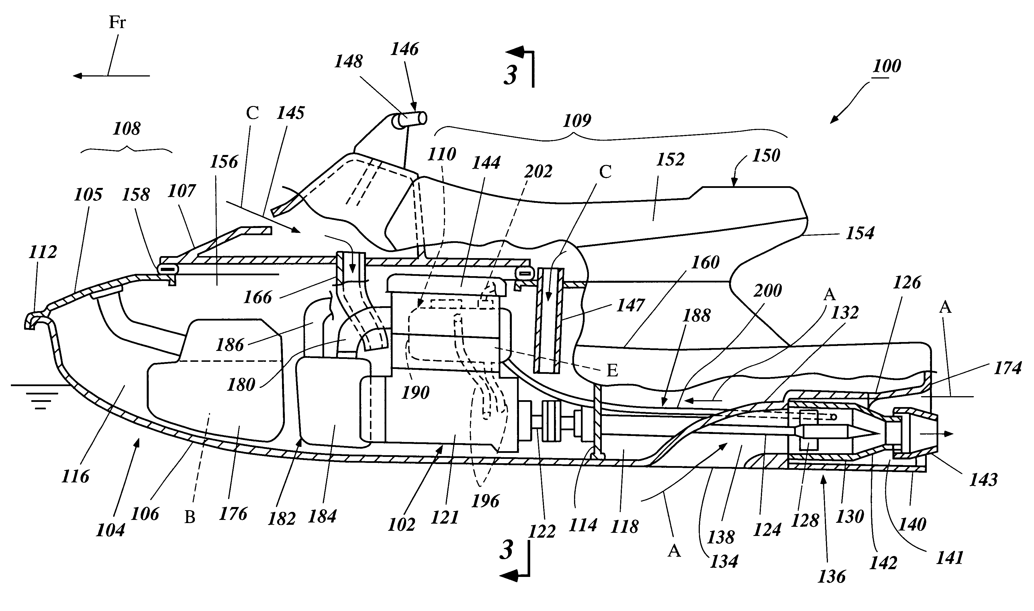
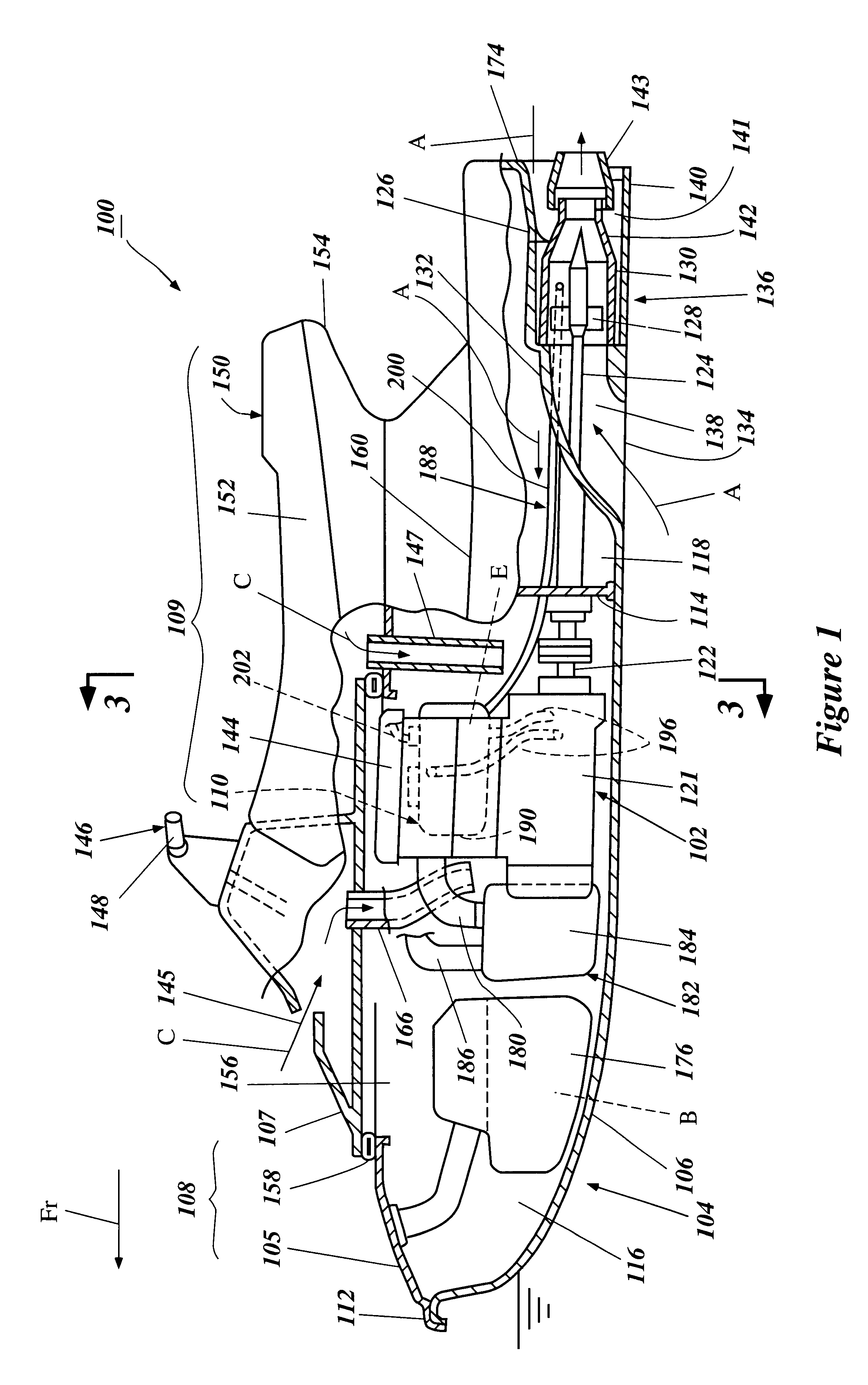
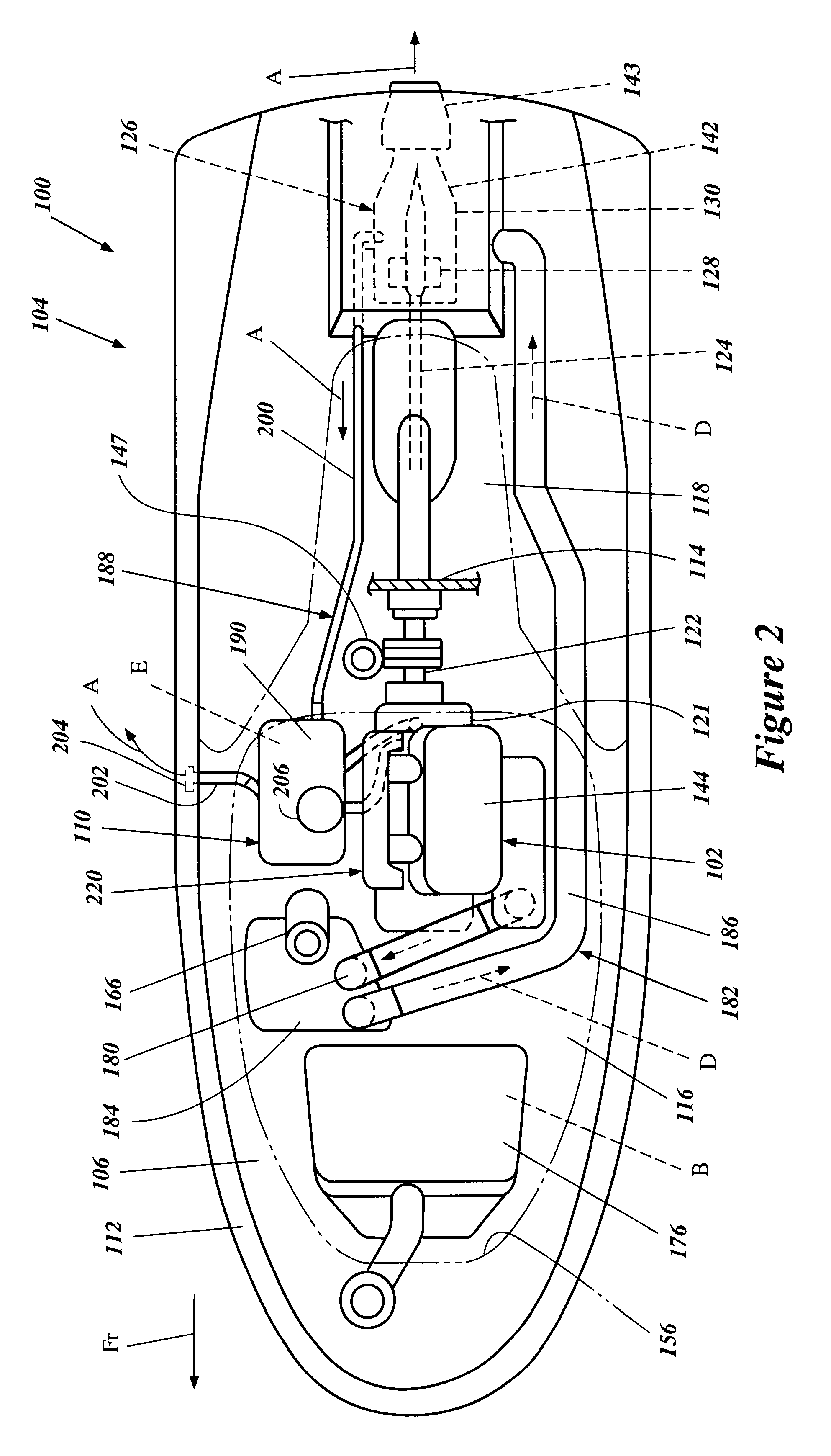
With reference to FIG. 1, a portion of a small watercraft, indicated generally by the reference numeral 100, is partially illustrated in cross-section. The watercraft 100 includes an arrangement of an engine 102 and a lubrication cooling system 110 within a hull 104 of the watercraft 100 in accordance with a preferred embodiment of the present invention. The engine 102 and lubrication cooling system 110 are arranged within the hull 104 in a manner which enhances the cooling of the engine lubrication. As a result, cooling of the lubrication results in a lower probability of lubrication viscosity break down thus reducing the chance of complete engine seizure.

Although the present invention is illustrated and described with reference to the illustrated embodiments, various other engine types and configurations may also be used with the present invention. Moreover, it is understood that the lubrication cooling system 110 can be used with other types of watercraft as well, for example, bu...


PUM


Abstract

A watercraft having a cooling system for the lubrication system of the engine, the cooling system including a reservoir, at least a portion of the reservoir being cooled by ambient water flowing through a cooling jacket in contact with the reservoir. Also disclosed is a watercraft having a cooling system for the lubrication system of the engine, the cooling system including a reservoir, at least a portion of the reservoir being cooled by direct and/or thermal contact with ambient water in which the watercraft floats.

Description

1. Field of the InventionThe present invention generally relates to a cooling system for a lubricating system of an internal combustion engine. More particularly, the present invention relates to a cooling system for a lubricating system of a watercraft engine that powers a water propulsion device.2. Description of Related ArtPersonal watercraft have become very popular in recent years. An enthusiasm for competition has grown with this popularity, and as a result personal watercraft have become increasingly fast. Many personal watercraft today are capable of speeds well in excess of 60 miles per hour. To attain such speeds, such watercraft are typically driven by high power output motors.Two-cycle engines commonly power personal watercrafts, as these engines have the advantage of being fairly powerful and relatively light and compact. One particular disadvantage of two-cycle engines though is emission content. Two-cycle engines exhaust large quantities of carbon monoxide and various...

Claims


Application Information

Patent Timeline
IPC IPC(8): B63H21/00B63H21/12B63H21/10B63H21/38B63B35/73
CPCB63H21/12B63B2770/00B63H21/10B63H11/08B63H21/383B63H21/386F01N13/12F01N2590/022
Inventor HATTORI, TOSHIYUKI
Owner YAMAHA MOTOR CO LTD
Why Eureka
Try Eureka