Method and apparatus for controlling drainage and irrigation of fields

a technology for irrigation and drainage, applied in mechanical equipment, transportation and packaging, service pipe systems, etc., can solve the problems of high elevations being depleted of water, affecting the drainage effect of irrigation water, and causing the land at higher elevations to be dry sooner

Inactive Publication Date: 2008-08-28
FURRER BRIAN SCOTT
View PDF15 Cites 14 Cited by
  • Summary
  • Abstract
  • Description
  • Claims
  • Application Information

AI Technical Summary

Benefits of technology

[0009]In each line (i.e., main and laterals), as the water level rises, the lowest valve in a series of interconnected valves will close first because surface water runs to a lower level and sub-surface water will normally accumulate at the lower levels first, if there are no pockets or ponds at the higher levels. In other words, for a given distance below the surface (e.g. three feet) water will normally rise to that given sub-surface level for valves located at lower elevations before it reaches that given distance for valves at higher elevations, all other factors being equal. The closing of the level-responsive valves progresses upwardly as the water level continues to rise at higher elevations. That is, as each valve at a lower level closes, the ambient water level at the next higher valve will increase until that valve also closes. This has the effect of “daming” the lines at progressively higher levels until, eventually, water is stored at the next higher level, not just in the valve, but in surrounding soil as well. This action is sometimes referred to herein as “terracing”, which is intended to mean that as additional water is available (assuming the manual valve is closed), the level at which sub-surface water will be stored will rise at higher elevations. In other words, without the level-responsive valves, all the water would flow through the drain lines down to the lowest elevation and not be retained at the higher elevations, whereas, with the present invention, as is desirable, the water is available directly to standing crops or for irrigation purposes at higher elevations.
[0010]In another aspect of the invention, the preferred level-responsive valve includes a flap type valve member which is hinged adjacent an opening in the inlet of the valve. The valve body includes an inlet section which is adapted to be coupled to a section of tile in a line. The valve flap is connected by means of a rigid link to a float which is received in a vertically oriented cylindrical reservoir, which is closed, but not sealed. The bottom of the reservoir houses the valve flap and couples to the inlet conduit, and includes an outlet adapted to be coupled to a downstream section of tile. As the water level rises in the valve housing, the float rises, ultimately closing the flap valve and shutting off the flow of water from the upstream tile section. The float member is not sealed against the inner wall of the cylindrical reservoir portion of the valve. Rather, rising water may flow about the float to a level above the float, after the valve is closed, and an aperture in the housing permits air to escape so that the movement of the float is not impeded.

Problems solved by technology

This type of system has certain disadvantages, primarily in that, as is well known, land at higher elevations is consistently drier than land at lower elevations.
Thus, water flows (underground) continuously to lower levels under gravity as long as the manual valve is open, thereby leaving higher elevations to be depleted of water and therefore become dry sooner than lower levels.

Method used


Image

  • Method and apparatus for controlling drainage and irrigation of fields
  • Method and apparatus for controlling drainage and irrigation of fields
  • Method and apparatus for controlling drainage and irrigation of fields

Examples


Embodiment Construction

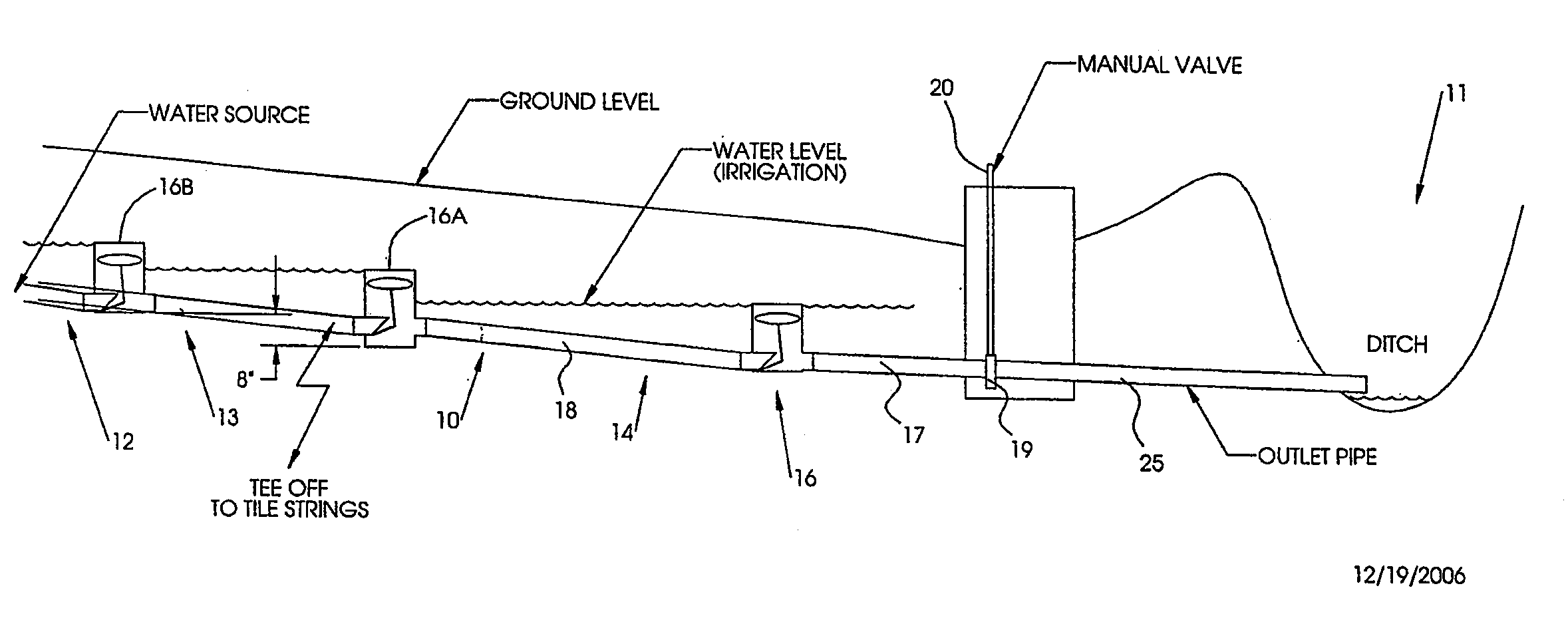
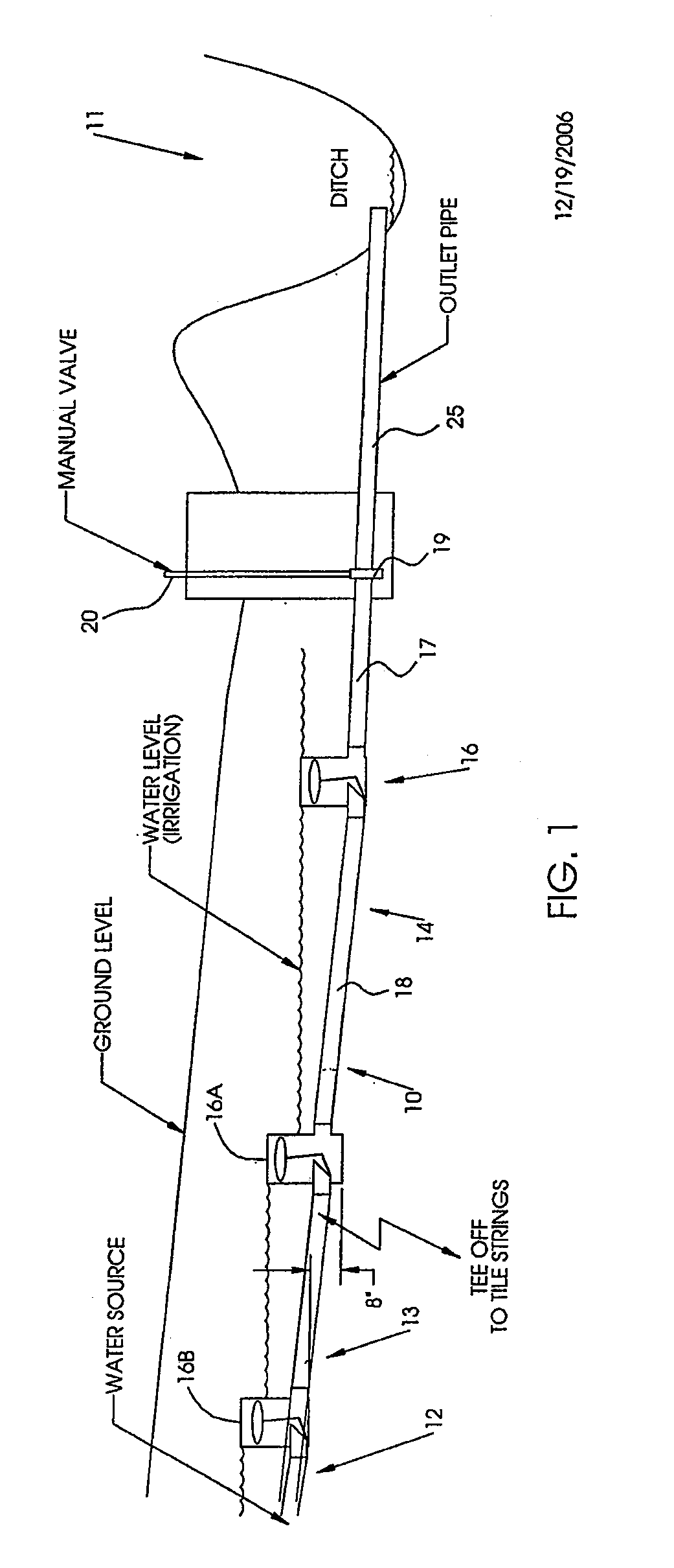
[0021]Referring first to FIG. 1, reference numeral 10 generally designates a single line for conducting subterranean water from a higher elevation (to the left in FIG. 1), to a lower elevation proceeding toward the right, and ending in discharging the water into a drainage ditch generally designated 11, or other suitable discharge waterway.

[0022]The overall system typically will include a method of controlling drainage / irrigation of a field comprising a network of interconnected drainage lines, which typically may include a main line and a number of lateral or auxiliary lines (“laterals”), extending from a higher elevation to a lower elevation and connecting together to form a network exiting through a manually controlled main valve to a drainage ditch or other water passage. The drawings show idealized installations. For example, the drain lines need not be parallel to the surface, nor is the depth of the lines critical. Maintaining good drainage, however, is desirable.

[0023]The la...


PUM


Abstract

A method of and apparatus for controlling drainage/irrigation of a field includes laying out a network of drainage tiles, which typically may include a main line and a number of lateral lines, extending from higher elevations to lower elevations and exiting through a manually controlled main valve to a drainage ditch.
A series of level-responsive valves are incorporated in the main and lateral lines at selected elevations. Each level-responsive valve is normally open until the ambient water level reaches a predetermined level relative to the valve. When the manual valve is closed and a certain level of water is reached adjacent a level-responsive valve, it causes that level-responsive valve to close, thereby cutting off drainage of higher elevations. When it is desired to retain water at higher elevations in a field, the manual valve is closed permitting water to accumulate and be retained at higher elevations by closing the level-responsive valves in sequence at progressively higher elevations as the level of retained water rises, thereby causing a cascading or “terracing” of water stored at upper levels. When the manual valve is opened, the field drains normally. The level-responsive valve may be a flotation valve. A modification of a flotation type level-responsive valve includes an overflow tube which permits excessive water at higher placement elevations to bypass the closed level-responsive valves, thereby permitting the field to drain under conditions of excess water into a standpipe at the manual valve.

Description

CROSS-REFERENCE TO RELATED APPLICATION[0001]This application claims priority of U.S. Provisional Application No. 60 / 903,687 filed on Feb. 27, 2007, entitled “Method and Apparatus for Controlling Drainage and Irrigation of Fields”.FIELD OF THE INVENTION[0002]The present invention relates to the control of sub-surface water levels and drainage in fields having different elevations, i.e., sloped. In particular, the invention is directed to agricultural fields, that is, fields used for growing crops.BACKGROUND OF THE INVENTION[0003]Systems are available for the draining of fields having different elevations. In general, the overall object is to maintain water at the root zone of the crop to promote growth, but to avoid excess water, which is harmful to crops. Typically, a manually operated valve is provided with a housing incorporating an outlet pipe which may feed a drainage ditch or other water tributary. The crop field in which it is desired to control the drainage, is provided with ...

Claims


Application Information

Patent Timeline
Patent Type & Authority Applications(United States)
IPC IPC(8): E02B11/00
CPCE02B13/02A01G25/00Y10T137/402
Inventor FURRER, BRIAN SCOTTSCHLATTER, RONALD GENEFURRER, G. JASON
Owner FURRER BRIAN SCOTT
Why Eureka
Try Eureka