Drive system

a technology of a drive system and a drive shaft, which is applied in the direction of engine starters, machines/engines, mechanical equipment, etc., can solve the problems of damage to one of the assemblies, the stator arrangement will be attracted to,

a technology of a drive system and a drive shaft, which is applied in the direction of engine starters, machines/engines, mechanical equipment, etc., can solve the problems of damage to one of the assemblies, the stator arrangement will be attracted to,

US6528918B2Inactive Publication Date: 2003-03-04ZF FRIEDRICHSHAFEN AG

Image

  • Drive system
  • Drive system
  • Drive system

Examples


Embodiment Construction

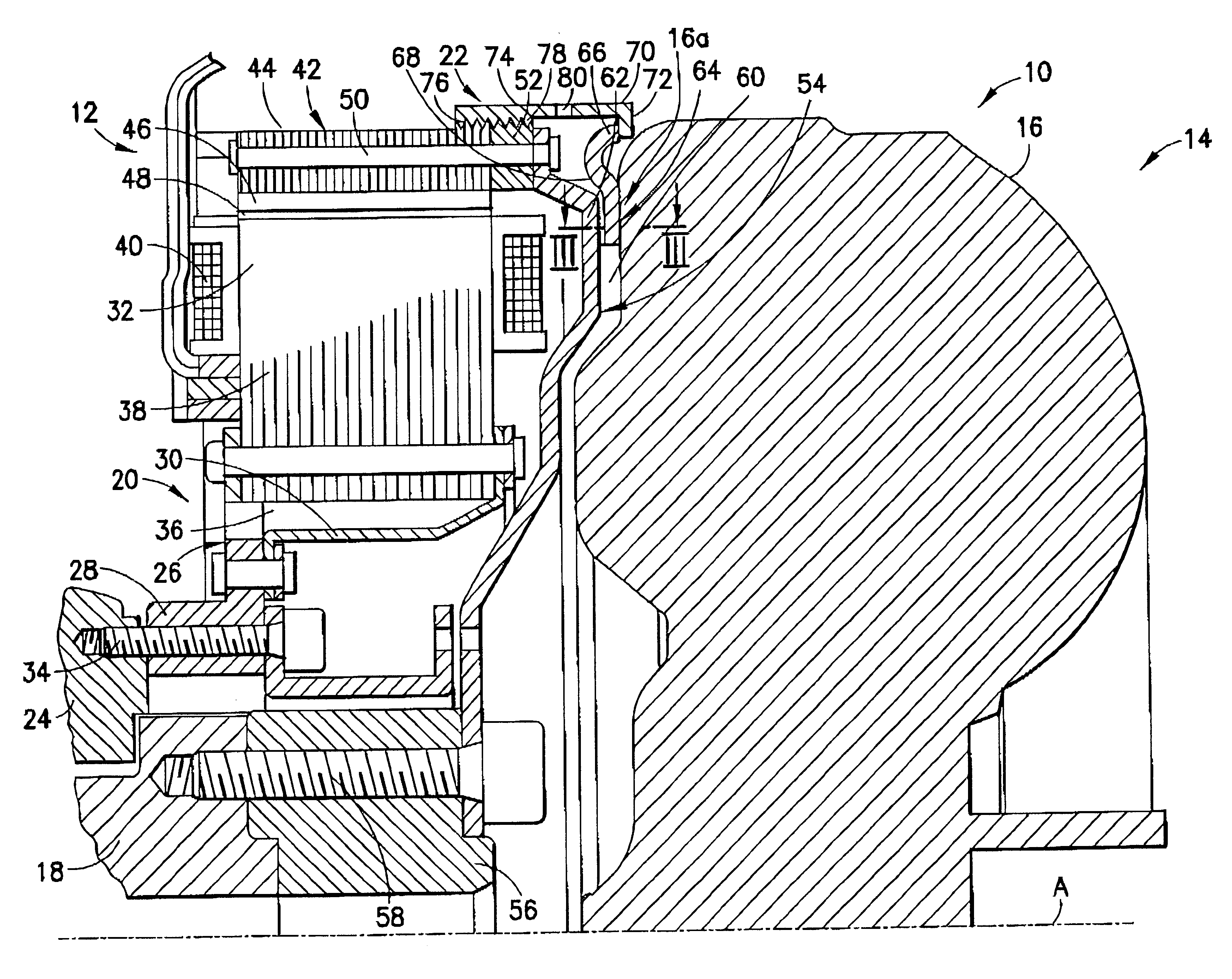
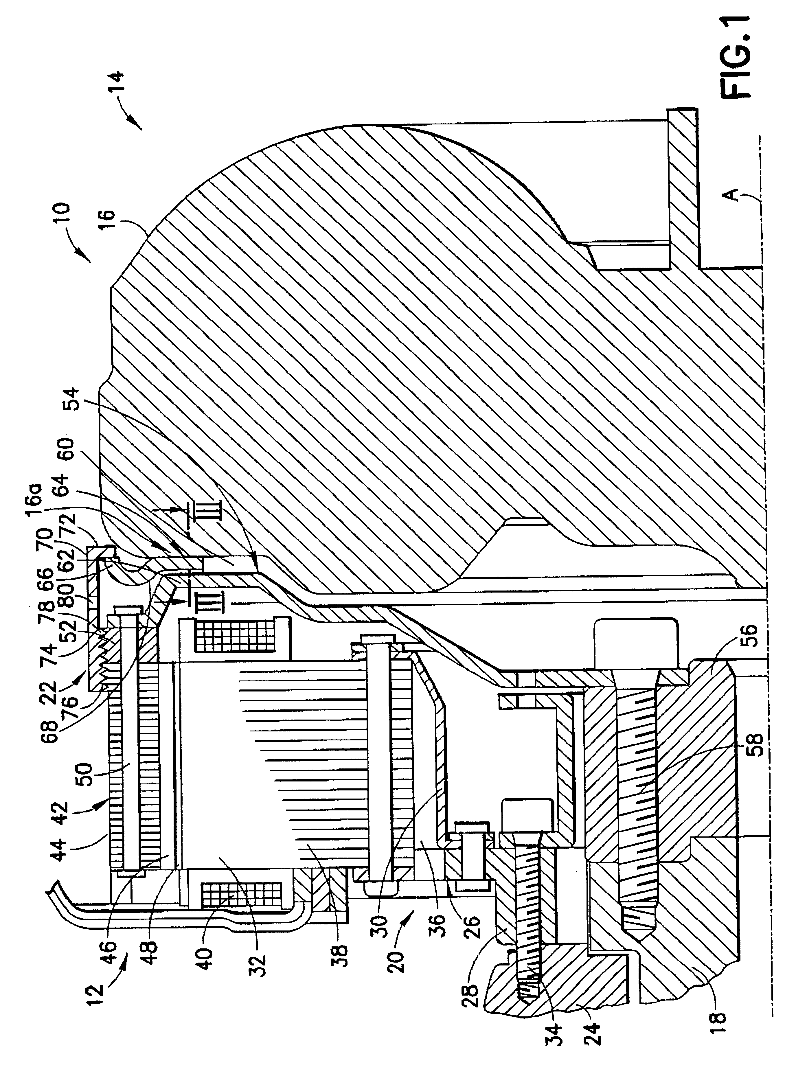
A drive system 10 according to the present invention is shown in FIG. 1 and includes an electric machine 12 and a coupling device 14. This coupling device 14 is illustrated only diagrammatically in the Figures and is shown in the form of its housing 16 visible to the outside. The coupling device 14 may, for example, comprise a hydrodynamic torque converter or a fluid coupling. The housing 16 is connected securely in terms of rotation in a way described below to a drive shaft 18 which may, for example, comprise a crankshaft. A turbine wheel (not shown in the Figures) arranged inside the housing 16 is connected to an output shaft such as, for example, a transmission input shaft. The design of such hydrodynamic coupling devices is known in the prior art and is not described further herein.

The electric machine 12 includes a stator arrangement 20 and a rotor arrangement 22. The stator arrangement 20 is connected to a fixed member or to a fixed assembly 24 such as, for example, an engine ...


PUM


Abstract

A drive system includes an electric machine with a rotor arrangement which is connectable to a drive shaft for joint rotation therewith and a stator arrangement. The drive system further includes a coupling device such as a hydrodynamic coupling device with an inlet region that is connectable to the drive shaft for joint rotation therewith. A coupling element that is connectable to the drive shaft supports a rotor interaction region of the rotor arrangement is connectable to the inlet region of the coupling device for joint rotation.

Description

1. Field of the InventionThe present invention relates to a drive system including an electric machine and a coupling device, the electric machine having stator arrangement and a rotor arrangement and the coupling device having an inlet region, wherein the rotor arrangement and the inlet region are connectable to a drive shaft for joint rotation about an axis of rotation.2. Description of the Related ArtIn drive systems having an electric machine with a rotor arrangement connected to a drive shaft, the electric machine typically comprises a starter / generator arrangement. In an active state, the electric motor acts as a starter arrangement to generate a torque which is transmitted to the drive shaft to start an internal combustion engine. In this active state, the electric machine may also be used to supplement the torque provided by the internal combustion engine by delivering a backup torque or a drive torque. In another state, the electric machine may also be used as a generator f...

Claims


Application Information

Patent Timeline
04 Mar 2003
Publication
US6528918B2
IPC
F02N11/04; H02K7/00; H02K7/18
CPC
F02N11/04; H02K7/1807; H02K7/006
Inventors
PAULUS-NEUES, JUTTA; KUNDERMANN, WOLFGANG