Dielectric resonance device, dielectric filter, composite dielectric filter device, dielectric duplexer, and communication apparatus

a technology of dielectric resonance and filter, which is applied in the direction of coupling devices, electrical devices, and dielectric filters. it can solve the problems of increasing cost, affecting the overall frequency characteristic of the resonance device, and raising the temperature characteristic of this mod

Inactive Publication Date: 2003-03-04
MURATA MFG CO LTD
View PDF7 Cites 15 Cited by
  • Summary
  • Abstract
  • Description
  • Claims
  • Application Information

AI Technical Summary

Problems solved by technology

Although the above-described temperature characteristics of the resonance frequencies can be improved through employment of a material of low linear expansion coefficient, such as invar or 42%-nickel iron alloy, this increases cost.
Further, when in addition a TE01.delta. mode of the dielectric core is utilized in a dielectric resonance device having a structure as s

Method used


Image

  • Dielectric resonance device, dielectric filter, composite dielectric filter device, dielectric duplexer, and communication apparatus
  • Dielectric resonance device, dielectric filter, composite dielectric filter device, dielectric duplexer, and communication apparatus
  • Dielectric resonance device, dielectric filter, composite dielectric filter device, dielectric duplexer, and communication apparatus

Examples


first embodiment

The structure of a dielectric resonance device according to the present invention will be described with reference to FIGS. 1 to 7.

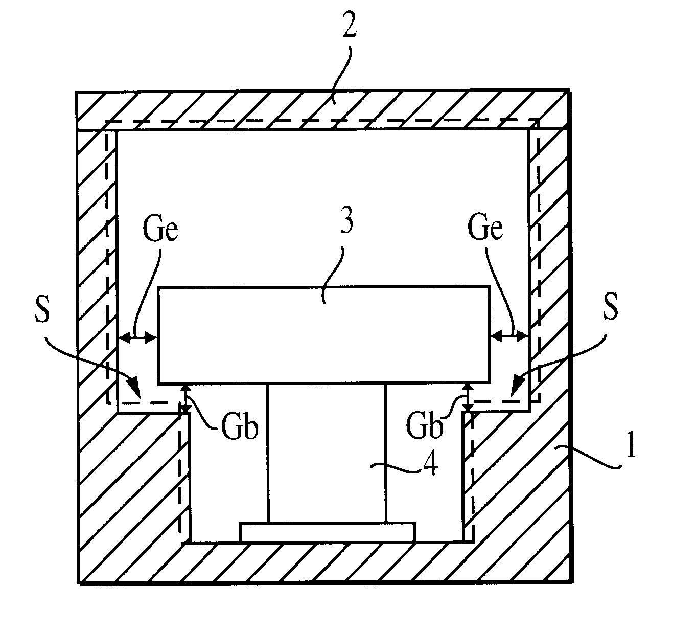
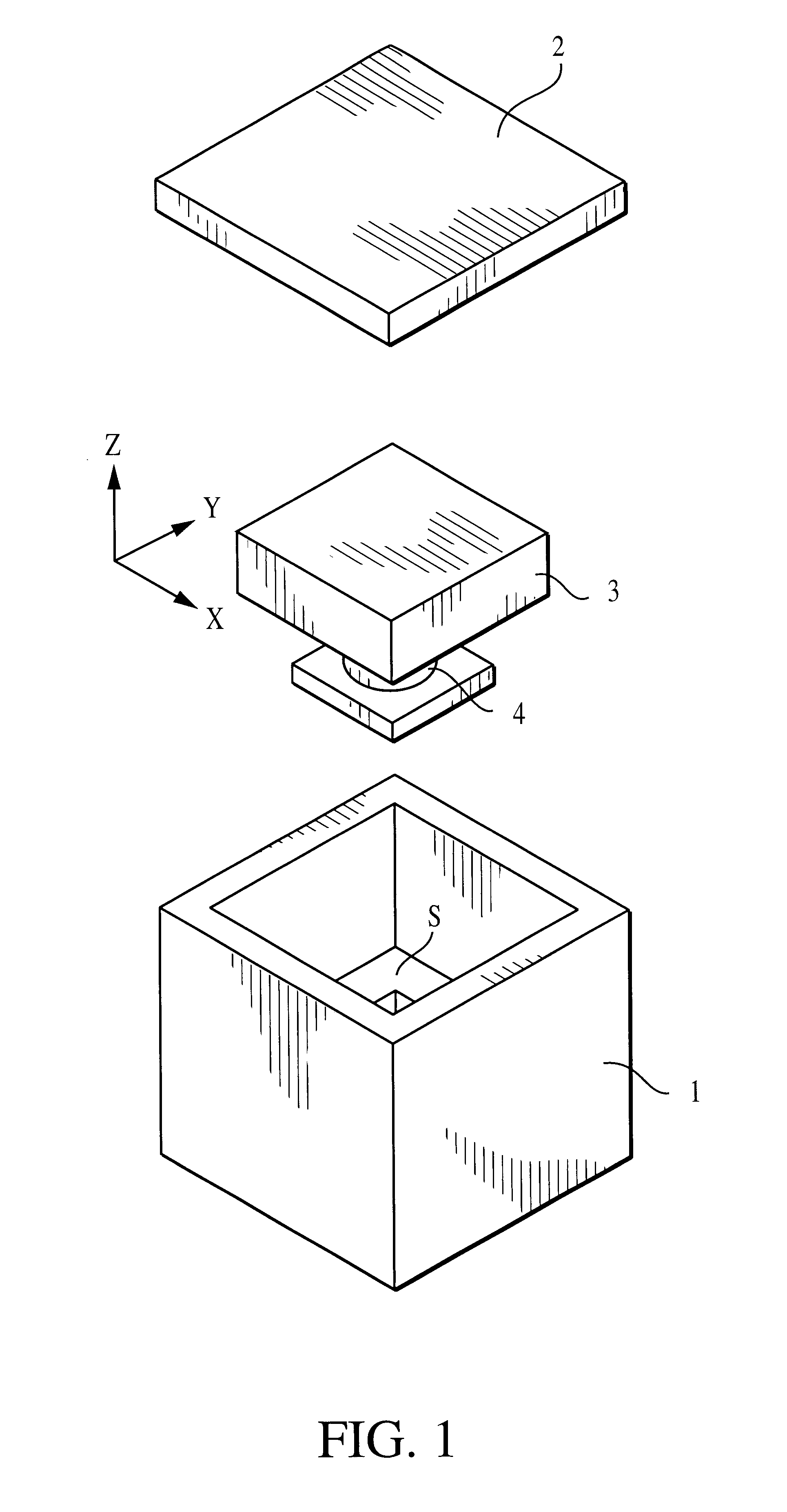
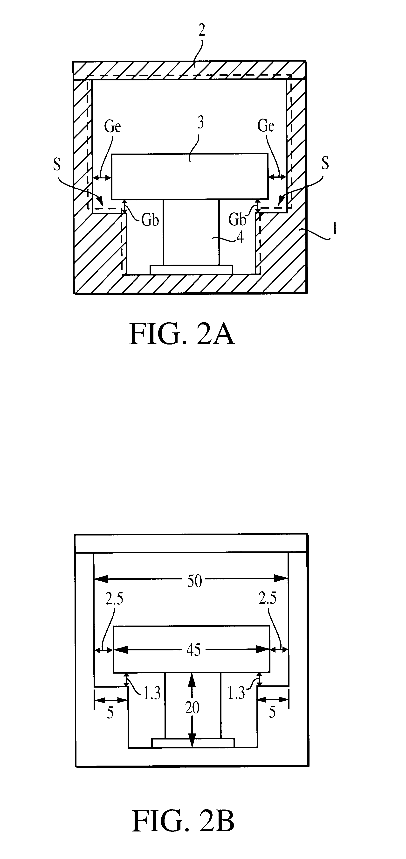
FIG. 1 is an exploded perspective view of the dielectric resonance device; and FIGS. 2A and 2B are each a vertical cross section of the dielectric resonance device at the center thereof. In these drawings, reference numeral 3 denotes a substantially parallelepipedic dielectric core formed of a dielectric material. Reference numeral 1 denotes a cavity body formed of a metal, and 2 denotes a cavity lid which is formed of a metal and covers the open face of the cavity body 1. The dielectric core 3 is bonded to the inner bottom face of the cavity body 1 via a support base 4. The bonding between the support base 4 and the dielectric core 3 is effected by use of adhesive or by means of baking. The cavity lid 2 is fixed to the open face of the cavity body 1 by use of screws (in the drawings, screws and tapped holes are omitted). It is to be noted that instead o...

second embodiment

The structure of a dielectric filter according to the present invention will be described with reference to FIGS. 8A to 8C and FIG. 9.

The dielectric filter differs from the dielectric resonance device of the first embodiment in that couplings for establishing coupling with resonance modes are added. FIG. 8A shows the positional relationship between the dielectric core and coupling loops serving as couplings. Two-dot chain lines schematically show the shape of the cavity. The structure of the cavity and the support structure of the dielectric core are the same as those used in the first embodiment.

FIG. 8B shows the electromagnetic field distributions of three resonance modes of the dielectric filter. FIG. 8C shows inter-stage couplings when the three resonance modes are used as a three-stage resonator. A coupling loop 7a shown in FIG. 7A establishes magnetic-field coupling with the TM01.delta..sub.-x mode, and a coupling loop 7b shown in FIG. 7A establishes magnetic-field coupling wi...

third embodiment

Next, the structure of a dielectric resonance device according to the present invention will be described with reference to FIGS. 10 and 11.

In the first embodiment, a stepped portion is formed inside the cavity in order to produce a capacitance between the surface of the stepped portion and the peripheral portion of the dielectric core. However, as shown in FIGS. 10 and 11, instead of the stepped portion, conductor plates may be provided on the inner wall surface of the cavity. FIG. 10 is an exploded perspective view of the dielectric resoancedevice; and FIG. 11 is a vertical cross section of the dielectric resonance device at the center thereof In these drawings, reference numeral 5 denotes conductor plates attached to the inner wall surface of the cavity body 1. That is, a capacitance is produced at each gap Gb between the peripheral portion of the support-base attachment surface of the dielectric core 3 and the corresponding conductive plate 4.

Even when conductive plates are prov...


PUM


Abstract

A dielectric resonance device includes a cavity body, a support base disposed inside the cavity body, and a dielectric core supported by the support base. A stepped portion is provided inside the cavity body such that a gap between the outer circumferential surface of the dielectric core and the inner wall surface of the cavity body and a gap between the peripheral portion of the support-base attachment surface of the dielectric core and the stepped portion change in opposite directions with temperature variation. Thus, variation with temperature in the resonance frequency of a TM01delta mode is suppressed.

Description

1. Field of the InventionThe present invention relates to a dielectric resonance device including a cavity and a dielectric core disposed therein, as well as to a dielectric filter, a composite dielectric filter device, a dielectric duplexer, and a communication apparatus, each of which utilizes the dielectric resonance device.2. Description of the Related ArtThe applicant of the present application has filed Japanese patent application Nos. 10-220371 and 10-220372 for inventions in relation to dielectric resonators which are compact and facilitate formation of a multi-stage resonator. In the dielectric resonators of these applications, a substantially parallelepipedic dielectric core is disposed within a substantially parallelepipedic cavity, and the dielectric core is resonated in multiple modes.Dielectric resonance devices in which a dielectric core is disposed within a cavity in an isolated manner typically employ a structure such that the dielectric core is supported at a prede...

Claims


Application Information

Patent Timeline
IPC IPC(8): H01P7/10H01P1/208H01P1/20H01P1/213H01P1/30
CPCH01P7/10H01P1/2084
Inventor KUBO, HIROYUKINAKATANI, YUKIHIRO
Owner MURATA MFG CO LTD
Why Eureka
Try Eureka