Evolutionary controlling system for motor

a technology of motor control and control system, applied in the direction of adaptive control, electric control, instruments, etc., can solve the problems of deteriorating user may not be satisfied, and the relationship between the primary output controller and the secondary output controller may not remain optimal

Inactive Publication Date: 2003-03-04
YAMAHA MOTOR CO LTD
View PDF10 Cites 27 Cited by
  • Summary
  • Abstract
  • Description
  • Claims
  • Application Information

AI Technical Summary

Problems solved by technology

Because preferences over the above output characteristics differ depending on the individual user, the user may not be satisfied if the relationship between the primary output-controller and the secondary output-controller is pre-fixed prior to shipment.
Further, in addition to the above problem, vehicles with driving power are used under various environmental conditions, and the conditions of the vehicles themselves differ greatly depending on the users.
Furthermore, driving power sources including peripheral parts deteriorate with time.
Thus, the relationship between the primary output-controller and the secondary output-controller may not remain optimum.

Method used


Image

  • Evolutionary controlling system for motor
  • Evolutionary controlling system for motor
  • Evolutionary controlling system for motor

Examples


Embodiment Construction

The output control system for vehicles equipped with drive power sources according to the present invention will be explained with reference to several embodiments indicated in the figures.

Basic Structures of Output Control System

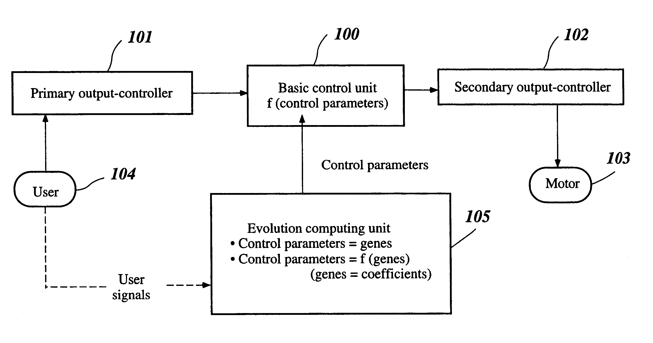
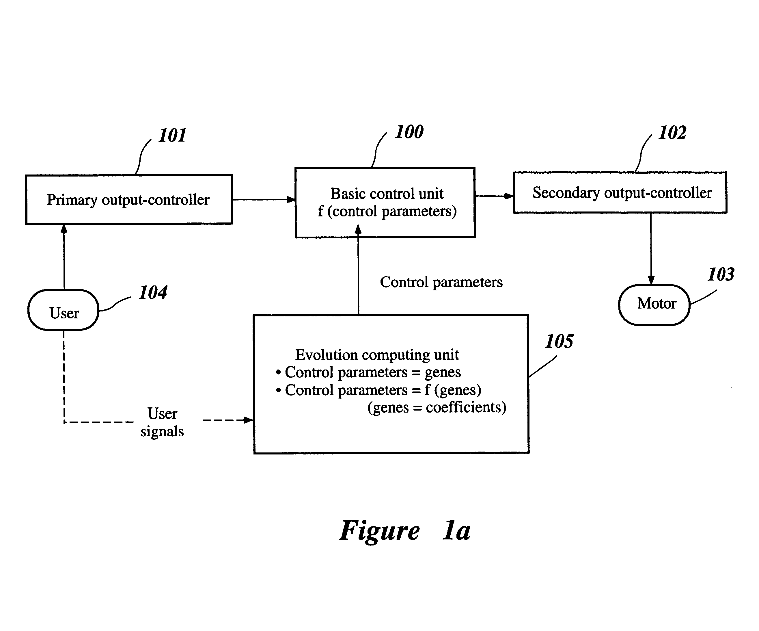
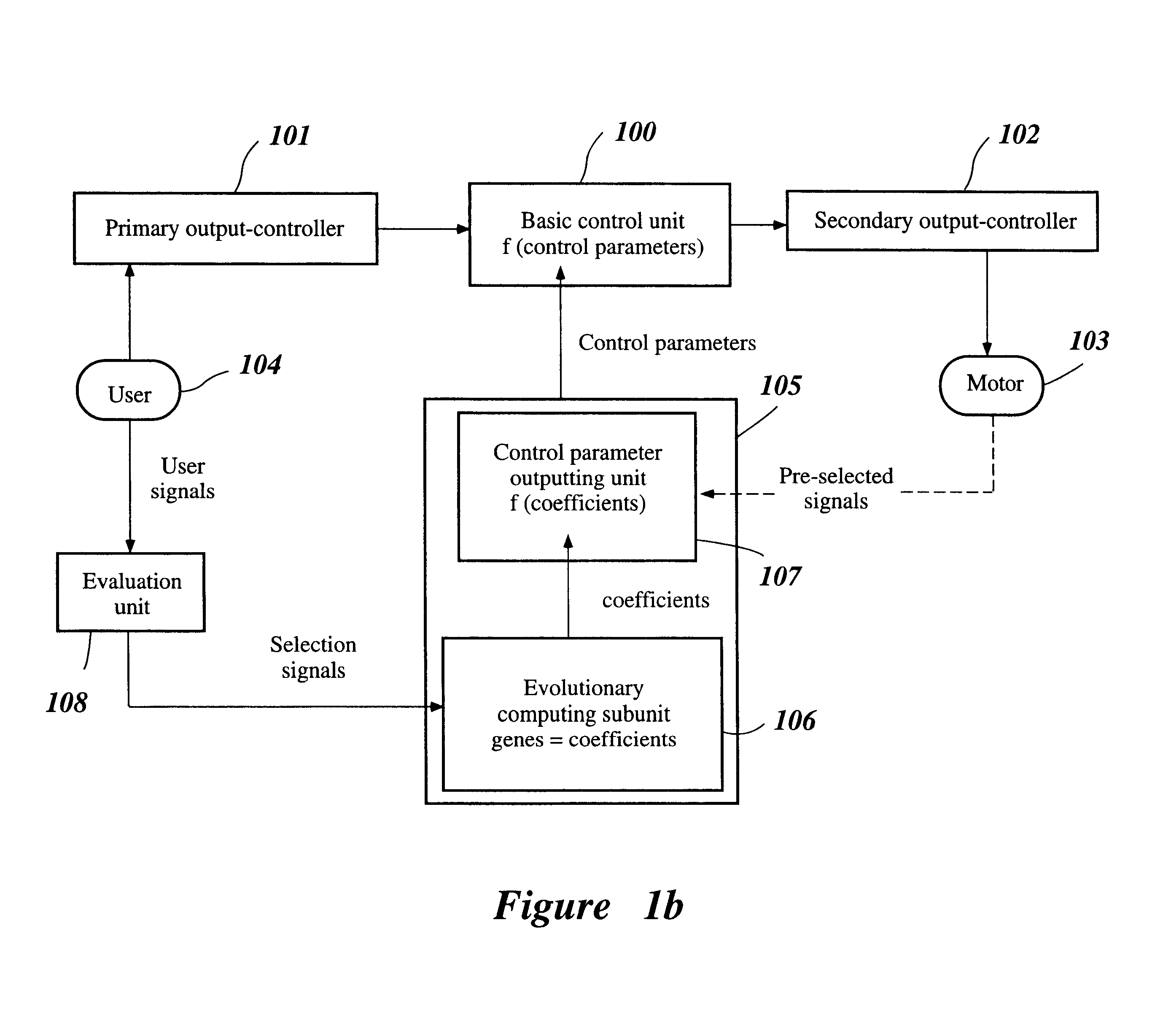
As shown in FIG. 1a, a system according to the present invention is for controlling performance of a motor 103 used by a user 104, which performance is controlled by a primary output-controller 101 manipulated by the user 104 and a secondary output-controller 102 directly operating the motor 103 based on the manipulated movement of the primary output-controller 101. The system comprises: (i) a basic control unit 100 for regulating the relationship between manipulated movement of the primary output-controller 101 and operated movement of the secondary output-controller 102, said relationship being regulated by control parameters; and (ii) an evolutionary computing unit 105 programmed to output control parameters to the basic control unit by selecting on a re...


PUM


Abstract

In an output controlling method for controlling output of a driving power source or motor installed in a vehicle, the relationship between a primary output-controller, which is manipulated by the user, and a secondary output-controller, which directly operates the motor, is regulated by control parameter subjected to evolution by using evolutionary computing based on at least one of the following: the user's characteristics, driving conditions, environmental changes, and deterioration of the drive power source with time. The evolution is conducted on-line or on a real-time basis. The primary output-controller includes an acceleration pedal or grip, and the secondary output-controller includes a throttle valve for an internal combustion engine or a running current controller for an electric motor.

Description

1. Field of the InventionThis invention relates to an evolutionary controlling system for motors, and particularly to that for controlling, in an evolutionary manner, output of motors installed in vehicles, for example.2. Description of Related ArtVehicles equipped with driving power such as combustion engines or electric motors are provided with primary output-controllers such as accelerator pedals, accelerator levers, or accelerator grips, so that a user can control output of the driving power by using the primary output-controller to directly operate a secondary output-controller such as throttle valves or current-carrying controllers for electric motors, thereby ultimately controlling output of the drive power.In the above, the operational movement of the primary output-controller and the operational movement of the secondary output-controller are fixed in a pre-set relationship before shipping the vehicle. Thus, for example, when the accelerator grip is manipulated to a certain...

Claims


Application Information

Patent Timeline
Patent Type & Authority Patents(United States)
IPC IPC(8): F02D41/00F02D41/24F02D11/10F02D41/20F02D9/02F02D41/34F02D45/00G05B13/02
CPCF02D11/105F02D41/2429F02D41/1405F02D2200/702F02D41/2477F02D2041/1432
Inventor YAMAGUCHI, MASASHIKAMIHIRA, ICHIKAITAKECHI, HIROAKI
Owner YAMAHA MOTOR CO LTD
Why Eureka
Try Eureka